Installation Guide
TG-0259_9 TM4 CO200-A3 Installation Guide
© Dana TM4 inc., 2020-2022
4.5.3 Suggested installation sequence
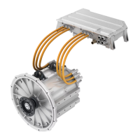
Several cables and harnesses are required for the MCU electrical connection. The system integrator will
define the final electrical connection sequences of the MCU and motor taking the complete installation into
consideration; this sequence for installing the MCU is given as an example and summarizes the electrical
connection sequence of the MCU.
IMPORTANT NOTE: Disable the high-voltage and auxiliary batteries before handling the product, or
connecting/disconnecting any cable, harness or tube.
1 Grounding strap, see Section 4.5.4.
2 Phase cables, see Section 4.5.5.
3 Motor sensor interface harness, see Section 4.5.6.
4 VMU interface harness between the MCU and the VMU, see Section 4.5.7.
5 High-voltage battery cables, see Section 4.5.8.
6 Cooling inlet/outlet hoses, see Section 4.4.
7 Auxiliary battery cables, see Section 4.5.9.
As specified earlier, the final installation sequence should be defined by the integrator according to the
application type. However, for user safety, the grounding strap should always be installed first and the
product should no longer be handled when the power source is enabled.
Note: Reverse sequencing is performed when removing the system from the vehicle; remove the grounding
strap last.
4.5.4 Grounding the system
The system must be securely grounded to ensure user safety in case of an insulation fault in the motor
and/or the MCU. An incorrectly grounded connection may result in motor/MCU functionality losses and
safety risks for the user.
IMPORTANT NOTE: Disable the high-voltage and auxiliary batteries before connecting or disconnecting
the ground.
4.5.4.1 Grounding strap recommendations
The integrator must consider the possibility of an insulation fault where the high-voltage battery current
would find a path through the grounding strap. The grounding strap or wire must be tin copper plated and
sized to support the maximum current of the high-voltage battery for a sufficient time for the high-voltage
battery fuse to open.
There are two main sizing considerations:
• The ground strap gauge must be at least half of the section of the HV cable, and
• The resistance between the chassis and other metallic parts of the vehicle must be less than 0.1 Ohm.
Full guidelines on how to achieve to this are given in the LV 123 standard [14].
Refer to Section 4.5.8.2 for the high-voltage battery fuse specification.


 To Next Page