Installation Guide
TG-0259_9 TM4 CO200-A3 Installation Guide
© Dana TM4 inc., 2020-2022
4.5.7 Connecting the VMU interface harness
Carefully read all safety instructions related to electrical installation (Section 4.5.1) and general information
for installing cables and harnesses in Section 4.5.2 before continuing with your integration.
IMPORTANT NOTE: Disable the high-voltage and auxiliary batteries before connecting or disconnecting
the VMU interface harness.
4.5.7.1 Preparing the VMU/ECU interface harness
A VMU or client ECU interface harness (not supplied by Dana TM4) is required between the Motor Control
Unit (MCU) and the Vehicle Management Unit (VMU). The VMU interface harness contains all required
signals to interface the MCU with the VMU including the enable signal and the CAN ports.
As vehicle integrators are able to connect the TM4 SUMO™ system to the VMU or ECU of their choice, the
integrator will have the responsibility of fabricating the VMU interface harness using wiring appropriate to
the specific installation environment. Dana TM4, therefore, does not deliver a VMU harness with the
system; only the plug and contacts listed and described in the Kit documentation [11] are included.
Note: Although the signal connectors are fully watertight when correctly installed, we strongly recommend
that you help direct water away from the connector heads by creating a drip loop with the cable in your
installation. Also, before connecting or reconnecting VCU harness connector, carry out a visual inspection
to ensure that the pins on both connectors of the harness are undamaged and that there is no dirt or debris
that might interfere with the contacts.
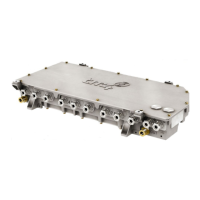
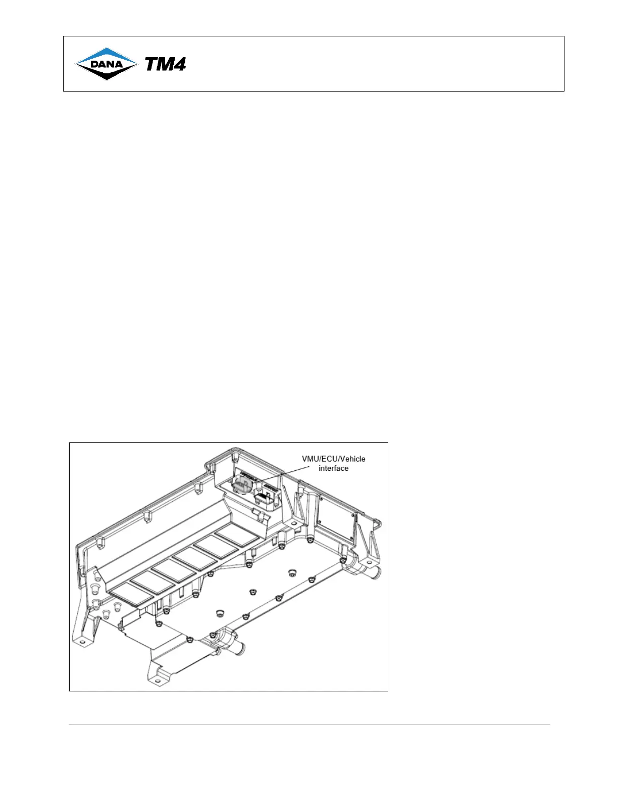
The VMU interface is located on the left side of the MCU next to the motor sensor interface (Figure 10).
Use the plug pinout specifications given in Table 6 and Figure 11 and refer to the documentation for
Kit-0110 [11] for full assembly instructions. Once the cable is prepared, connect it to the MCU, see
Section 4.5.7.3.
Figure 10 VMU/ECU interface location – Underside of the MCU
 Loading...