Installation Guide
TG-0259_9 TM4 CO200-A3 Installation Guide
© Dana TM4 inc., 2020-2022
1 Introduction
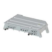
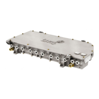
The TM4 CO200 motor control unit (MCU) from the SUMO™ series has been designed for light and mid-
duty EV trucks and buses.
The TM4 CO200 MCU utilizes the latest technology of automotive grade insulated-gate bipolar transistors
(IGBT) to deliver the industry’s highest specific power and current densities.
1.1 Purpose
The information given in this Installation Guide takes you through the steps required to safely and securely
install the TM4 CO200 motor control unit (MCU) in your vehicle as part of the TM4 SUMO™ system.
1.2 Scope
This guide is divided as follows:
• Introduction – general information about the MCU, safety warning format, definitions and document
reference information.
• Transport and storage conditions – guidelines on environmental conditions to be respected during
product storage and transport.
• Receiving and unpacking – general guidelines on how to safely unpack, lift and inspect the product.
• Installing the MCU in the vehicle – how to safely install and secure the product.
• Customer service – Dana TM4 customer service contact details.
1.3 What’s new
This guide has been modified as follows:
• Added information on alternative 6-phase cable mappings – standard and reversed,
see Section 4.5.5.2.1.
1.4 Comparison between CO200-A1 and A3
Several improvements have been made to the A3; the following list summarizes the main changes for
customers who have already used the A1 MCU:
• Design changes: See the Product Interface drawing [8] for details.
• The IGBT overflow hole previously located on the base of the casing has been removed to prevent
water infiltration.
• Slight change to casing dimensions.
• Strain relief added to the casing to offer support to communication cables.
• Coolant hose ID increased from ¾ to 1 inch.
• New motor sensor connector, see Section 4.5.6.
• New VMU connectors, see Section 4.5.7.
• New Quick Connect Phase and HV cable assemblies, see Figure 7 and Figure 14.
• Software/functionality changes: Also see Software Release Notes for your system.
• The new Dual Digital Signal Processor (DSP) used in the A3 has an impact on options available in
the Device Communication Configuration window in TM4 ODIN, see Section 4.6.2.4 for currently
supported devices.