Installation Guide
TG-0259_9 TM4 CO200-A3 Installation Guide
© Dana TM4 inc., 2020-2022
4.5.5.2.1 Modifying the phase cable mapping
Cable configuration can be modified to suit your integration. To provide greater flexibility when integrating
the system into the vehicle and to prevent the cables from touching or crossing over each other when
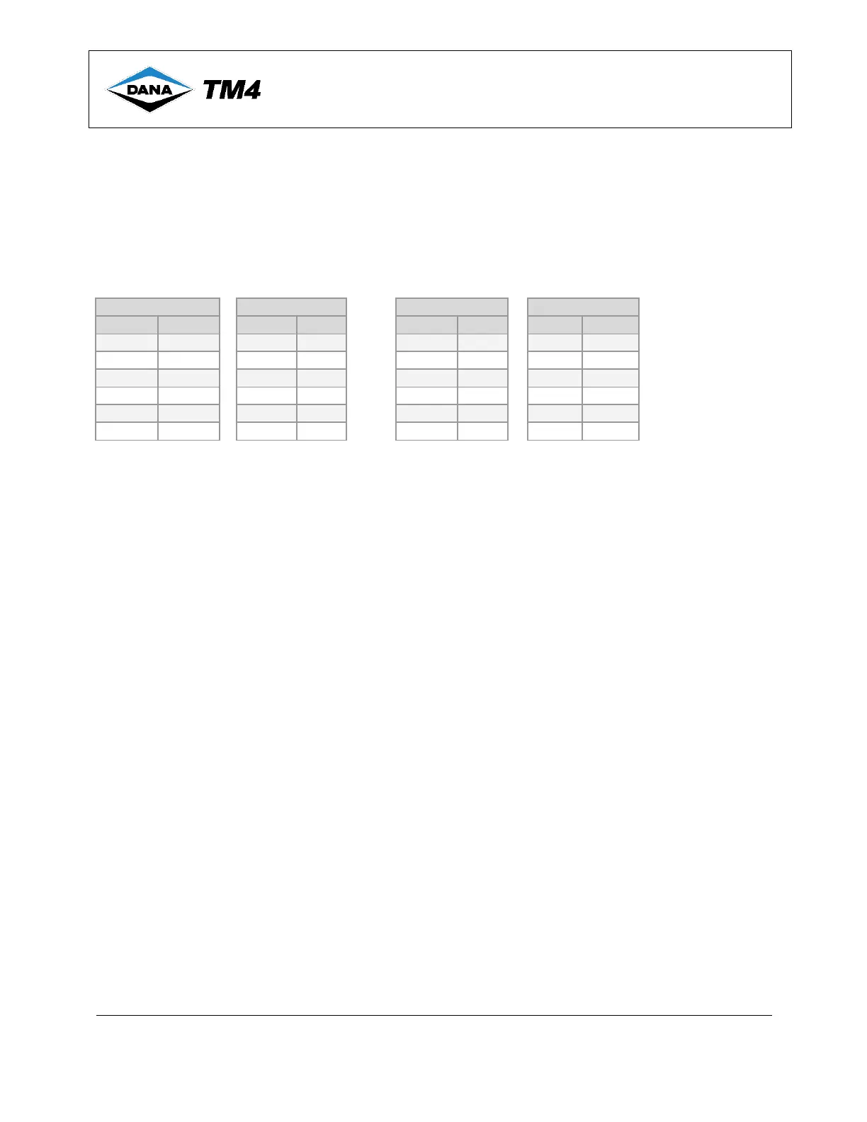
connecting the motor to the MCU, we recommend the phase cable mappings shown in Table 4.
• Standard: Cables connected with logical/letter number sequence (A1-1; B1-2; / A1-4; B1-5, etc.).
• Reversed: Cables connected with reversed letter/number sequence (A1-6; B1-5; / A1-3; B1-2, etc.).
Table 4 6- Phase cable installation mappings
Note If the reversed connection scenario is chosen, the PhaseCableReversed parameter must be set to 1, and the
DrvParameters.Save parameter must be set to 1. For more information, refer to the product Operations and
Maintenance Guide [5] for your system.
When purchasing a Quick Connect cable assembly, you can select from a number of possible
configurations [12] including Standard and Reversed phase order.
4.5.6 Motor sensor interface harness
Note: Carefully read all safety instructions related to electrical installation (Section 4.5.1) and general
information for installing cables and harnesses in Section 4.5.2 before continuing with your integration.
IMPORTANT NOTE: Disable the high-voltage and auxiliary batteries before connecting or disconnecting
the motor sensor interface harness.
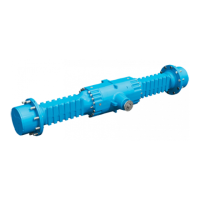
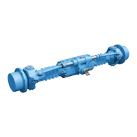
A motor sensor interface harness is required between the motor and the MCU; when using Dana TM4
products together in a system, you can order a motor sensor interface harness of a pre-determined length
to be delivered with the system, contact Customer Service for available lengths and part numbers.
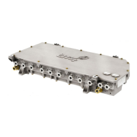
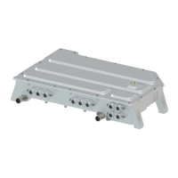
The motor sensor interface is located on the left side of the MCU next to the VMU interface (Figure 9).
For vehicle integrators who wish to connect the TM4 MCU to the motor of their choice (non-TM4), the
integrator will have the responsibility of fabricating the motor sensor interface harness using wiring
appropriate to the specific installation environment. In that case, TM4 does not deliver a motor sensor
harness with the system.
For TM4 motors, see Table 5 for the plug pinout information for the two types of connectors currently
available.
When the cables are not supplied by Dana TM4, see Section 4.5.6.1 for pinout information required for
harness preparation.
 Loading...