Installation Guide
TG-0259_9 TM4 CO200-A3 Installation Guide
© Dana TM4 inc., 2020-2022
Notes:
• Two supply pins (15 and 8) are used for redundancy but as they are physically connected in the MCU
only one correctly sized fuse is required to protect the VAUX supply in case of fault.
• While designing the VMU/ECU interface harness, plan a connector or a mechanism to connect the
diagnostic tool (TM4 ODIN) to CAN1 and/or CAN2 (CAN2 is not used in all versions of the system).
See Section 4.5.10 for termination information.
• Ensure that the connector heads respect the IP6K9K ratings to prevent water infiltrating into the
system.
• There are no recommended wire colours.
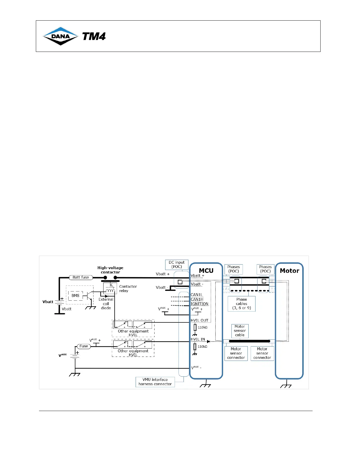
4.5.7.2 HVIL signals
The system will draw power and recharge the high-voltage battery based on the torque request and will
limit the maximum charge/discharge currents as specified using the associated CAN protocol message.
However, in case of hazardous behaviour or maintenance of the traction system, an HVIL hardware signal
should be connected for safety purposes.
When the system is fully installed and connected, the HVIL internal loop is closed therefore resulting in a
short circuit between its two input pins. The HVIL signal is used to open the high-voltage battery contactor
when its internal loop is opened during product maintenance or repair (e.g. removal of MCU cover or
disconnection of motor sensor cable) thereby protecting the user.
See Figure 12 for the suggested HVIL safety circuit to implement the necessary safety feature.
4.5.7.2.1 Suggested HVIL safety circuit
Disclaimer: Note that if you choose not to implement this circuit, TM4 is not responsible for any effects of
hazardous behaviour or system malfunction during maintenance or due to a situation requiring an
emergency stop.
Figure 12 Suggested HVIL safety circuit
 Loading...