Installation Guide
TG-0259_9 TM4 CO200-A3 Installation Guide
© Dana TM4 inc., 2020-2022
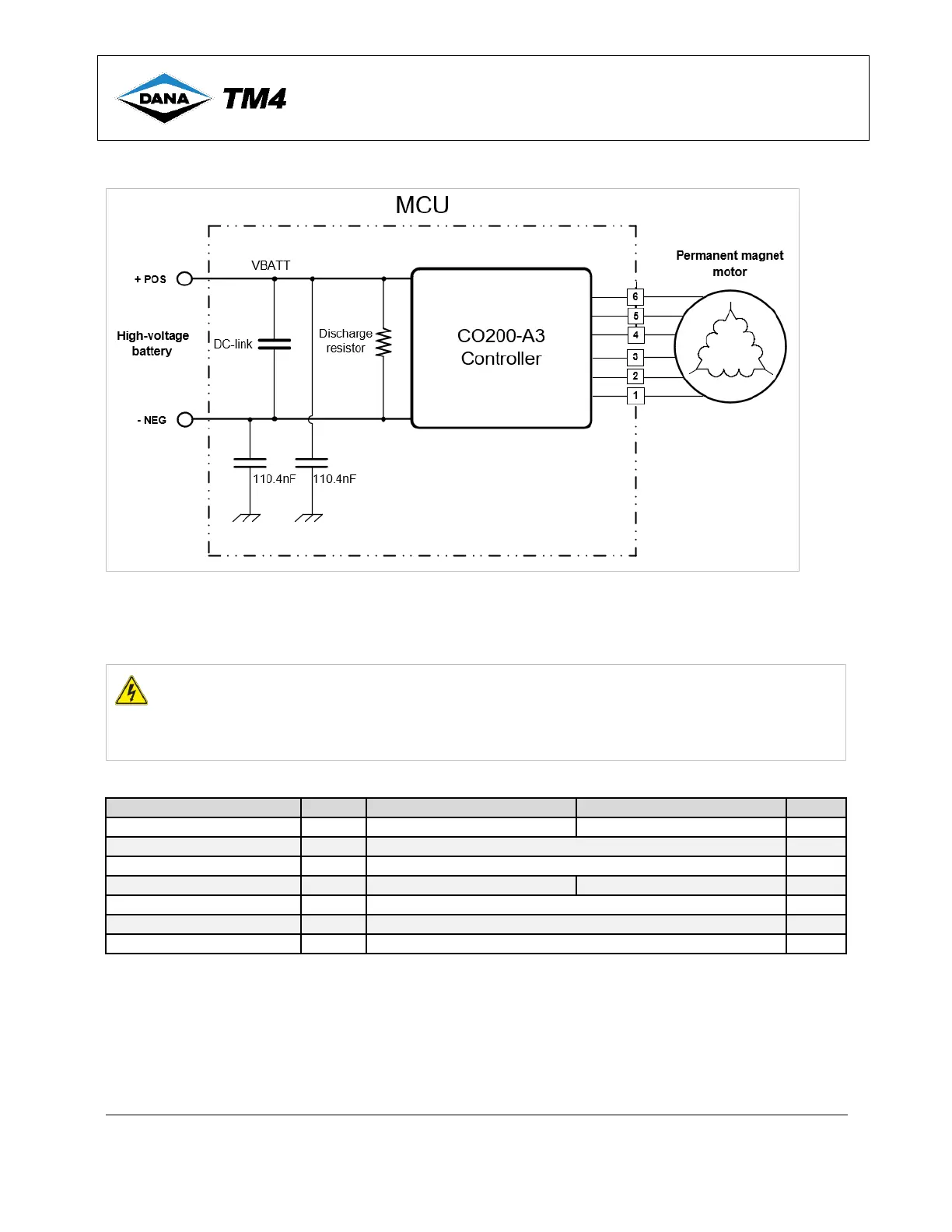
Figure 13 MCU high-voltage impedance sensor circuit
4.5.8.5 High-voltage battery cable assembly specifications
The high-voltage battery must be connected to the MCU using specific cable assemblies. Refer to Table 10
for the cable specifications.
WARNING The high-voltage cables MUST be shielded.
The external cables used for high voltage must be orange and shielded; the high voltage and level of
current delivered by this product can be lethal.
Failure to shield the high-voltage cables will result in non-compliance with EMI regulatory requirements.
Table 10 High-voltage battery – Cable specifications
Values for single DC pair
Under-hood contaminant resistant
Depends on the high-voltage battery voltage
Continuous current rating
Notes: All power cables must be compliant with ISO-6722
1. The wire size or wire wall material can be adapted to fit required use.
2. Depending on the location of the wires, a wire tubing (orange split loom) can be used to prevent abrasion or other
effects that could damage the wires.
3. Based on a temperature of 85 °C.
4. The colour orange is recommended for safety purposes when handling high voltage levels.
5. The external cables used for high-voltage must be shielded.
 Loading...