Installation Guide
TG-0259_9 TM4 CO200-A3 Installation Guide
© Dana TM4 inc., 2020-2022
4.5.8.6 Calculating high-voltage cable length
While calculating the length of cable required for the high-voltage battery cable installation, the integrator
must allow for the length of the crimped cable that is installed inside the MCU casing (for cables with lugs)
or inside the connector head for the Quick Connect cables. These measurements are shown on the
harness specification document [10] for your installation.
Note: When operating the system in a test environment using a DC source, the high-voltage battery
cable should be at least 3 m in length, inclusive of the cable inside the MCU. This is to avoid problems of
resonance between the low output impedance sources, the low inductance of a shorter cable and the
internal capacity of the MCU.
When using a high-voltage battery, whether in a test environment or installed in a vehicle, there is no
minimum cable length requirement.
4.5.8.7 Preparing the high-voltage battery cables
There are two types of cables that can be used with the CO200-A3 and in both cases the integrator can
prepare the cables following the instructions provided by TM4:
• Regular (with lugs), see the cable specification documents [9] for your installation.
Note we recommend that to prevent damage to the product, before installing the cables that you label
each one with either a plus or a minus to indicate polarity.
• Quick Connect, see the assembly instructions [13]. These cables can also be purchased pre-
assembled. See [12] to select the appropriate harness configuration for your integration.
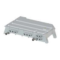
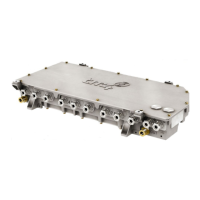
4.5.8.8 Installing the high-voltage battery harness
WARNING The high-voltage power source must not be connected until the installation is completed and the
plugs are firmly attached.
The high voltage and level of current delivered by this product can be lethal.
Using the prepared harness or harnesses in the product variant using the two HV battery connectors, refer
to the product interface drawing [8] for illustrated cable installation information. See Figure 14 for location of
high-voltage connectors on MCU casing.
 Loading...