Installation Guide
TG-0259_9 TM4 CO200-A3 Installation Guide
© Dana TM4 inc., 2020-2022
4.5.6.1 Preparing the motor sensor interface harness
Dana TM4 provides the plug and contacts required for integrators to provide their own motor sensor
interface harness to connect an A3 MCU to an A3 motor; pinout information is given in Table 5.
Note: If you are using the MCU A3 in a system with an A2 or A2.5 motor (with a Type 1 connector), pre-
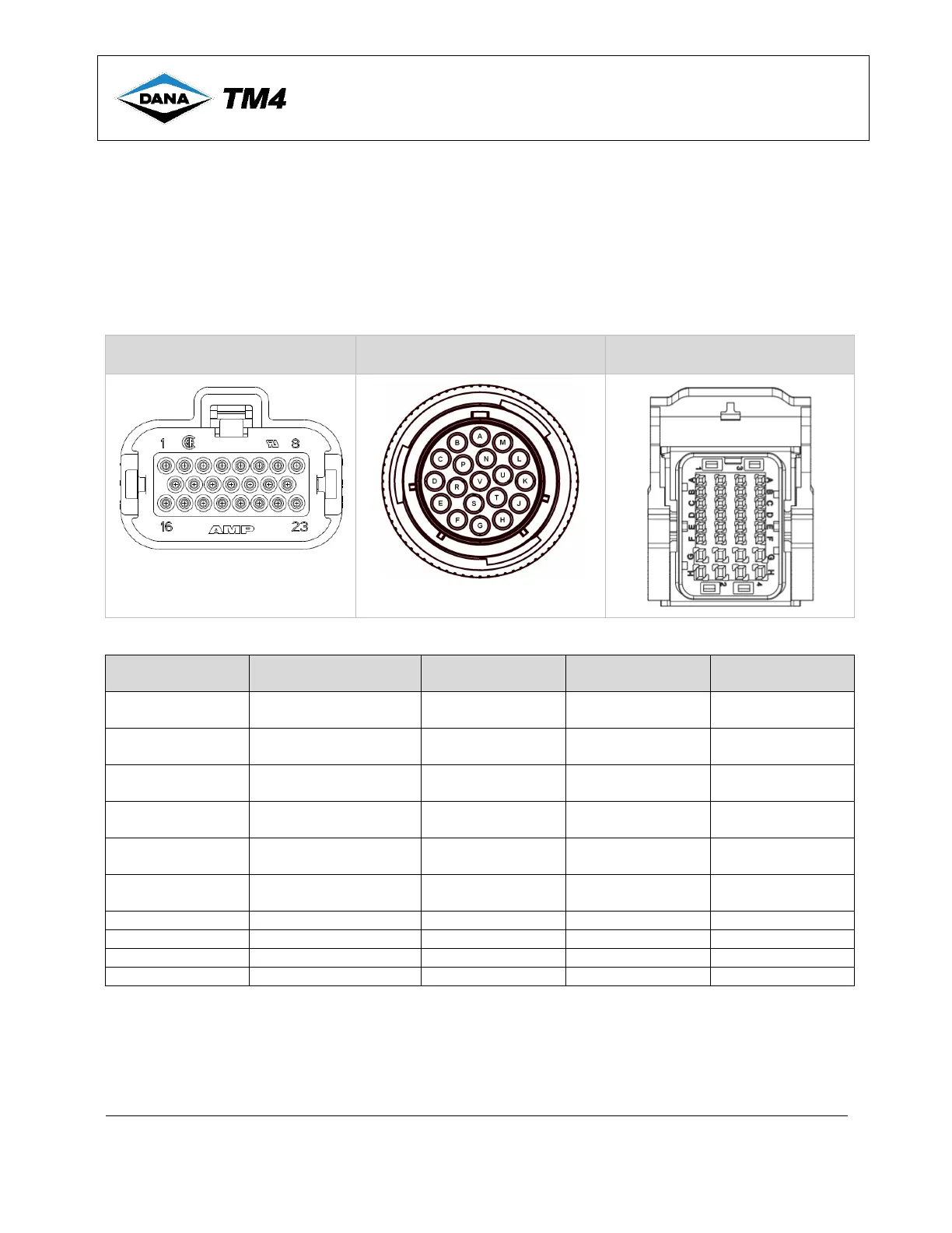
assembled harnesses are available for purchase from TM4. See Figure 8 to identify your connector type
and then contact TM4 for information on how to purchase the correct harness.
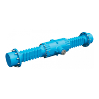
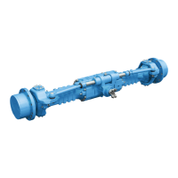
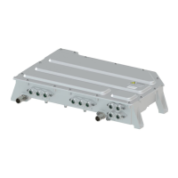
Figure 8 Connector head identification
TM4 MCU A3 TM4 Motor Type 1 TM4 Motor Type 2
Table 5 Motor sensor connector pinout mapping from TM4 MCU A3 to TM4 motors
Notes:
1. See Figure 8 for images of connectors referred to in Table 5.
2. Twisted wire pairs are grouped together in Table 5.
3. For non-TM4 motors, by default, the system is set to read two temperature sensors, if a system requires only
one temperature sensor to be read, set the NbMotorTempSensor parameter to 1 or an error will be returned
at system start-up.


 To Next Page