Installation Guide
TG-0259_9 TM4 CO200-A3 Installation Guide
© Dana TM4 inc., 2020-2022
List of figures
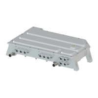
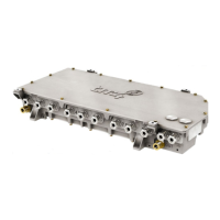
Figure 1 Position of vent on base of MCU casing .............................................................. 14
Figure 2 Mounting points – External view of top and base of the MCU ............................. 14
Figure 3 Parallel cooling system ........................................................................................ 16
Figure 4 Serial cooling system ........................................................................................... 16
Figure 5 Coolant inlet/outlet locations on the MCU ............................................................ 17
Figure 6 Grounding point – MCU – Hole location .............................................................. 21
Figure 7 Phase cable identification .................................................................................... 22
Figure 8 Connector head identification .............................................................................. 24
Figure 9 Motor sensor interface location – Base of the MCU ............................................ 25
Figure 10 VMU/ECU interface location – Underside of the MCU ........................................ 26
Figure 11 VMU interface harness – Plug pinout – 1-776228-1 – Black coding ................... 27
Figure 12 Suggested HVIL safety circuit .............................................................................. 28
Figure 13 MCU high-voltage impedance sensor circuit ....................................................... 32
Figure 14 High-voltage battery – Cable connector location ................................................. 34
Figure 15 Auxiliary battery – Fuse block diagram ................................................................ 35
Figure 16 INV-HP2HV_0206-XX (A3): CAN bus termination ............................................... 36
Figure 17 INV-HP2HV_0206-18 / INV-HP2HV_0206-20: CAN bus termination .................. 36
Figure 18 Device Communication Configuration – CO200-A3 (CAN1) ............................... 40
 Loading...