Area Title Functions
8 Control circuitry
•
Input
power, internal
processing, output,
and motor
current are monitored to
provide efficient operation
and control
•
User interface and external
commands are monitored and
performed
•
Status output and control can
be provided
Table 1.3 Legend to Illustration
1.3
1.5
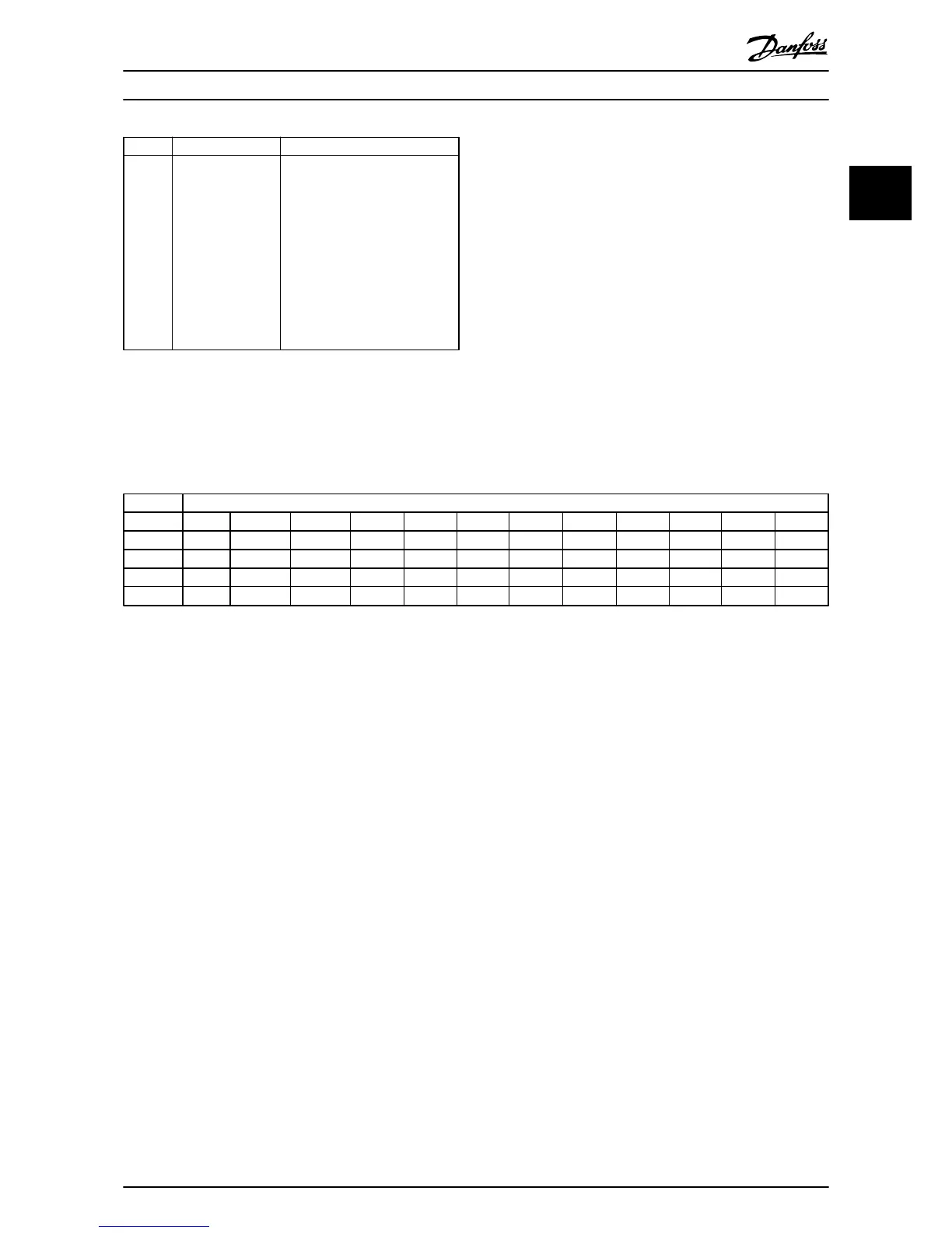
Frame Sizes and Power Ratings
References
to
frames sizes used in this manual are defined in Table
1.4.
Frame Size
[kW]
[V] A2 A3 A4 A5 B1 B2 B3 B4 C1 C2 C3 C4
200-240 1.1-2.2 3.0-3.7 1.1-2.2 1.1-3.7 5.5-11 15 5.5-11 15-18.5 18.5-30 37-45 22-30 37-45
380-480 1.1-4.0 5.5-7.5 1.1-4.0 1.1-7.5 11-18.5 22-30 11-18.5 22-37 37-55 75-90 45-55 75-90
525-600 n/a 1.1-7.5 n/a 1.1-7.5 11-18.5 22-30 11-18.5 22-37 37-55 75-90 45-55 75-90
525-690 n/a 1.1-7.5 n/a n/a n/a 11-30 n/a 11-37 n/a 37-90 45-55 n/a
Table 1.4 Frames Sizes and Power Ratings
Introduction
VLT
®
HVAC Drive Operating Instructions
MG11AI02 - VLT
®
is a registered Danfoss trademark
7
1 1