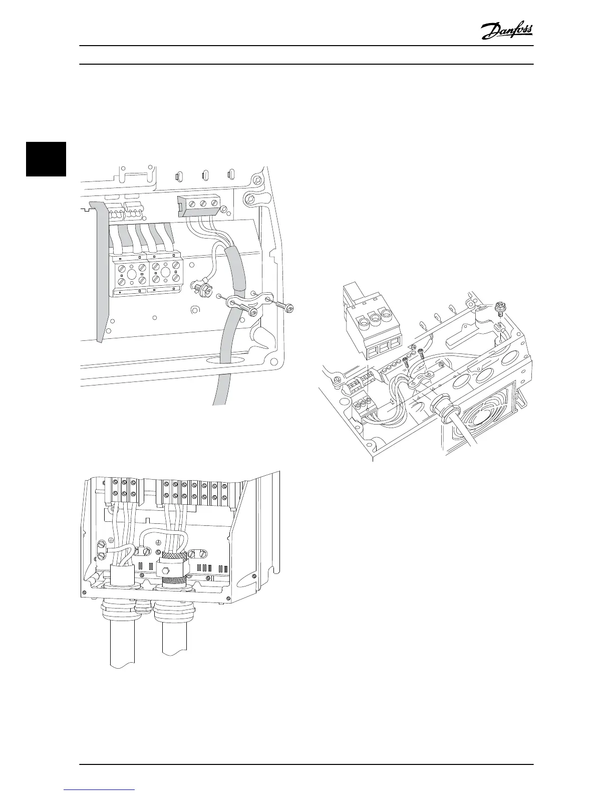
2.4.3.3 Motor Connection for B1 and B2
First terminate the motor earth, then place motor U, V and
W wires in terminal
and tighten. Ensure that the outer
insulation of the motor cable is removed under the EMC
clamp.
Illustration 2.14 Motor Connection for B1 and B2
2.4.3.4 Motor Connection for C1 and C2
91
L1
92
L2
93
L3
96
U
97
V
98
W
88
DC-
89
DC+
81
R-
8
R+
130BA390.11
99
95
Illustration 2.15 Motor Connection for C1 and C2
First terminate the motor earth, then Place motor U, V and
W wires in terminal
and tighten. Ensure that the outer
insulation of the motor cable is removed under the EMC
clamp.
2.4.4 AC Mains Connection
•
Size wiring based upon
the input current of the
frequency converter. For maximum wire sizes see
10.1 Power-dependent Specifications.
•
Comply with local and national electrical codes
for cable sizes.
•
Connect 3-phase AC input power wiring to
terminals L1, L2, and L3 (see Illustration 2.16).
•
Depending on the configuration of the
equipment, input power will be connected to the
mains input terminals or the input disconnect.
L 1
L 2
L 3
91
92
93
130BT336.10
Illustration 2.16 Connecting to AC Mains
•
Ground the cable in accordance with grounding
instructions provided in 2.4.2 Earth (Grounding)
Requirements
•
All frequency converters may be used with an
isolated input source as well as with ground
reference power lines. When supplied from an
isolated mains source (IT mains or floating delta)
or TT/TN-S mains with a grounded leg (grounded
delta), set 14-50 RFI Filter to OFF. When off, the
internal RFI filtercapacitors between the chassis
and the intermediate circuit are isolated to avoid
damage to the intermediate circuit and to reduce
earth capacity currents in accordance with IEC
61800-3.
Installation
VLT
®
HVAC Drive Operating Instructions
16 MG11AI02 - VLT
®
is a registered Danfoss trademark
22
Phone: 800.894.0412 - Fax: 888.723.4773 - Web: www.ctiautomation.net - Email: info@ctiautomation.net