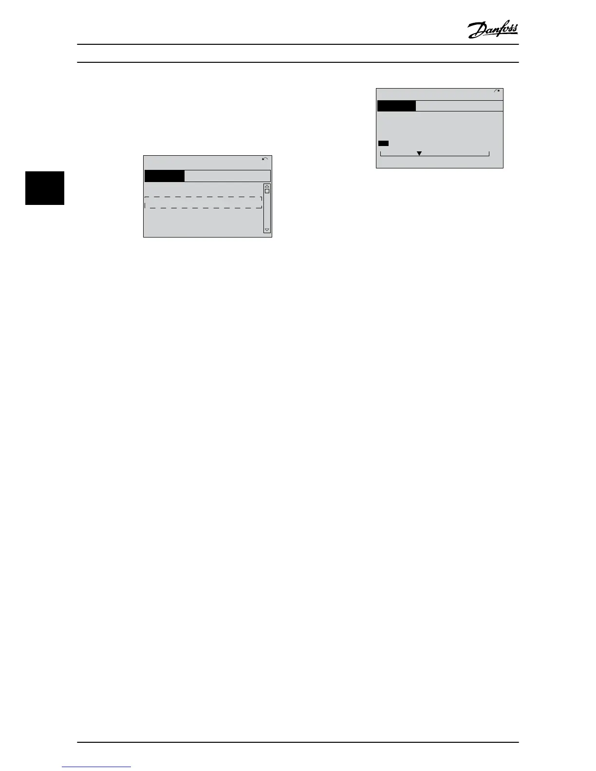
Illustration 3.4 Quick Menus
8. Select language and press [OK].
9. A jumper wire should be in place between
control terminals 12 and 27. If this is the case,
leave 5-12 Terminal 27 Digital Input at factory
default. Otherwise select No Operation. For
frequency converters with an optional Danfoss
bypass, no jumper wire is required.
10.
3-02 Minimum Reference
11.
3-03 Maximum Reference
12.
3-41 Ramp 1 Ramp Up Time
13.
3-42 Ramp 1 Ramp Down Time
14.
3-13 Reference Site. Linked to Hand/Auto* Local
Remote.
3.4 Asynchronous Motor Setup
Enter the motor data in parameters 1-20/1-21 to 1-25. The
information
can be found
on the motor nameplate.
1.
1-20 Motor Power [kW] or 1-21 Motor
Power [HP]
1-22 Motor Voltage
1-23 Motor Frequency
1-24 Motor Current
1-25 Motor Nominal Speed
Illustration 3.5 Motor Setup
3.5 PM Motor Setup
CAUTION
Do only use PM
motor with fans and pumps.
Initial Programming Steps
1.
Activate
PM motor operation
1-10 Motor
Construction, select [1) PM, non salient SPM
2.
Make sure to set 0-02 Motor Speed Unit to [0] RPM
Programming motor data.
After selecting PM motor in 1-10 Motor Construction, the
PM motor-related parameters in parameter groups 1-2*,
1-3* and 1-4* are active.
The information can be found on the motor nameplate
and in the motor data sheet.
Following parameters must be programmed in the listed
order
1.
1-24 Motor Current
2.
1-26 Motor Cont. Rated Torque
3.
1-25 Motor Nominal Speed
4.
1-39 Motor Poles
5.
1-30 Stator Resistance (Rs)
Enter line to common stator winding resistance
(Rs). If only line-line data are available, divide the
line-line value with 2 to achieve the line to
common (starpoint) value.
It is also possible to measure the value with an
ohmmeter, which will also take the resistance of
the cable into account. Divide the measured
value by 2 and enter the result.
6.
1-37 d-axis Inductance (Ld)
Enter line to common direct axis inductance of
the PM motor.
If only line-line data are available, divide the line-
line value with 2 to achieve the line-common
(starpoint) value.
It is also possible to measure the value with an
inductancemeter, which will also take the
inductance of the cable into account. Divide the
measured value by 2 and enter the result.
7.
1-40 Back EMF at 1000 RPM
Start Up and Functional Tes...
VLT
®
HVAC Drive Operating Instructions
28 MG11AI02 - VLT
®
is a registered Danfoss trademark
33