2.4.5 Control Wiring
•
Isolate
control wiring from
high power
components in the frequency converter.
•
If the frequency converter is connected to a
thermistor, for PELV isolation, optional thermistor
control wiring must be reinforced/double
insulated. A 24 V DC supply voltage is
recommended.
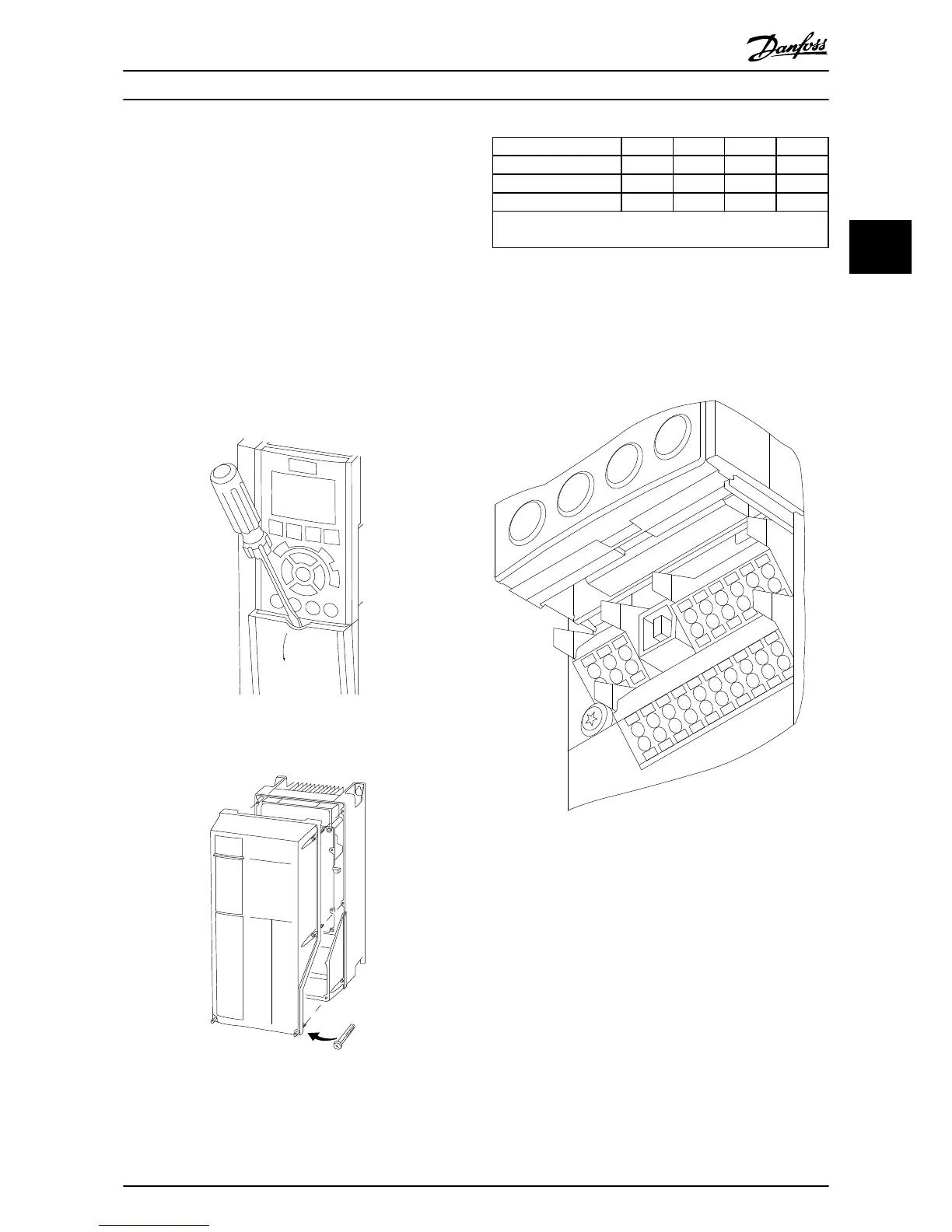
2.4.5.1 Access
•
Remove
access cover plate
with a screw driver.
See Illustration 2.17.
•
Or remove front cover by loosening attaching
screws. See Illustration 2.18.
Illustration 2.17 Control Wiring Access for A2, A3, B3, B4, C3 and
C4 Enclosures
Illustration 2.18 Control Wiring Access for A4, A5, B1, B2, C1 and
C2 Enclosures
See Table 2.3 before
tightening the
covers.
Frame IP20 IP21 IP55 IP66
A3/A4/A5 - - 2 2
B1/B2 - * 2.2 2.2
C1/C2/C3/C4 - * 2.2 2.2
* No screws to tighten
-
Does not exist
Table 2.3 Tightening Torques for Covers (Nm)
2.4.5.2 Control Terminal Types
Illustration 2.19 shows the removable
frequency converter
connectors. Terminal functions and default settings are
summarized in Table 2.4.
1
4
2
3
130BA012.11
61
68
69
39
42
50
53
54
55
12
13
18
19
27
29
32
33
20
37
Illustration 2.19 Control Terminal Locations
•
Connector 1 provides four
programmable digital
inputs terminals, two additional digital terminals
programmable as either input or output, a 24 V
DC terminal supply voltage, and a common for
optional customer supplied 24 V DC voltage
•
Connector 2 terminals (+)68 and (-)69 are for an
RS-485 serial communications connection
•
Connector 3 provides two analog inputs, one
analog output, 10 V DC supply voltage, and
commons for the inputs and output
•
Connector 4 is a USB port available for use with
the frequency converter
Installation
VLT
®
HVAC Drive Operating Instructions
MG11AI02 - VLT
®
is a registered Danfoss trademark
17
2 2
Phone: 800.894.0412 - Fax: 888.723.4773 - Web: www.ctiautomation.net - Email: info@ctiautomation.net