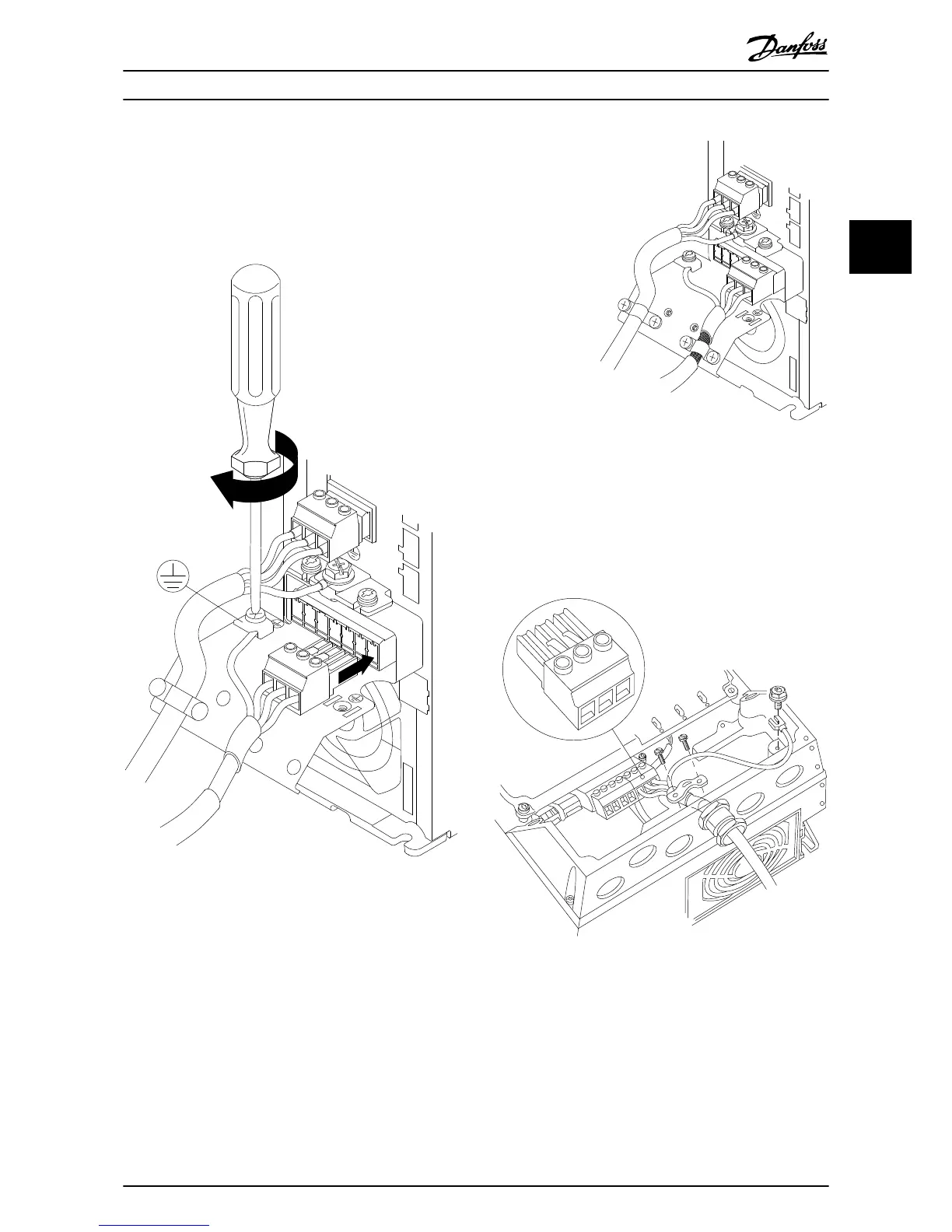
2.4.3.1 Motor Connection for A2 and A3
Follow these drawings step by step for connecting the
motor to the frequency
converter.
1. First terminate the motor earth, then place motor
U, V and W wires in plug and tighten.
MAINS
L1 L2 L3
91 92 93
- LC +
RELAY 1 RELAY 2
+DC
BR-
B
+DC BR- BR+ U V W
99
V
W
MOTOR
130BA265.10
Illustration 2.11 Motor Connection for A2 and A3
2.
Mount
cable clamp to
ensure 360° connection
between chassis and screen, note the outer
insulation of the motor cable is removed under
the clamp.
130BA266.10
+DC
BR-
B
MAINS
L1 L2
92
RELAY 1 Y 2
99
- LC -
V
W
MOTOR
Illustration 2.12 Cable Clamp Mounting
2.4.3.2 Motor Connection for A4/A5
First terminate the motor earth, then place motor U, V and
W wires in terminal
and tighten. Ensure that the outer
insulation of the motor cable is removed under the EMC
clamp.
Illustration 2.13 Motor Connection for A4/A5
Installation
VLT
®
HVAC Drive Operating Instructions
MG11AI02 - VLT
®
is a registered Danfoss trademark
15
2 2
Phone: 800.894.0412 - Fax: 888.723.4773 - Web: www.ctiautomation.net - Email: info@ctiautomation.net