EasyManuals Logo
Home>Danfoss>Media Converter>102

Danfoss 102 User Manual

Danfoss 102
94 pages
To Next Page IconTo Next Page
To Previous Page IconTo Previous Page
Page #51 background imageLoading...
Page #51 background image
6 Application Set-Up Examples
6.1 Introduction
NOTE
When
the optional safe
stop feature is used, a jumper wire
may be required between terminal 12 (or 13) and terminal
37 for the frequency converter to operate when using
factory default programming values.
The examples in this section are intended as a quick
reference for common applications.
Parameter settings are the regional default values
unless otherwise indicated (selected in
0-03 Regional Settings)
Parameters associated with the terminals and
their settings are shown next to the drawings
Where switch settings for analog terminals A53 or
A54 are required, these are also shown
6.2 Application Examples
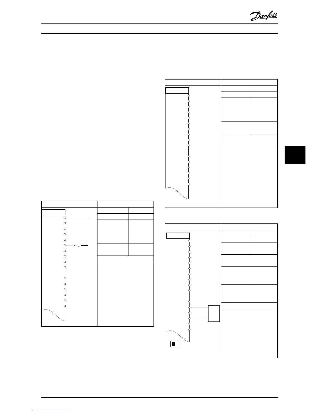
Parameters
FC
+24 V
+24 V
D IN
D IN
D IN
COM
D IN
D IN
D IN
D IN
+10 V
A IN
A IN
COM
A OUT
COM
12
13
18
19
20
27
29
32
33
37
50
53
54
55
42
39
130BB929.10
Function Setting
1-29 Automatic
Motor
Adaptation
(AMA)
[1] Enable
complete
AMA
5-12 Terminal 27
Digital
Input
[2]* Coast
inverse
* =
Default Value
Notes/comments:
Parameter
group 1-2* must
be set
according to motor
D IN 37 is an option.
Table 6.1 AMA with T27 Connected
Parameters
FC
+24 V
+24 V
D IN
D IN
D IN
COM
D IN
D IN
D IN
D IN
+10 V
A IN
A IN
COM
A OUT
COM
12
13
18
19
20
27
29
32
33
37
50
53
54
55
42
39
130BB930.10
Function Setting
1-29 Automatic
Motor
Adaptation
(AMA)
[1] Enable
complete
AMA
5-12 Terminal 27
Digital
Input
[0] No
operation
* =
Default Value
Notes/comments:
Parameter
group 1-2* must
be
set according to motor
D IN 37 is an option.
Table 6.2 AMA without T27 Connected
Parameters
FC
+24 V
+24 V
D IN
D IN
D IN
COM
D IN
D IN
D IN
D IN
+10
V
A IN
A IN
COM
A OUT
COM
12
13
18
19
20
27
29
32
33
37
50
53
54
55
42
39
A53
U - I
-10 - +10V
+
-
130BB926.10
Function Setting
6-10 Terminal 53
Low Voltage
0.07 V*
6-11 Terminal
53
High Voltage
10 V*
6-14 Terminal
53
Low Ref./Feedb.
Value
0 Hz
6-15 Terminal
53
High Ref./Feedb.
Value
50 Hz
* =
Default Value
Notes/comments:
D
IN 37 is
an option.
Table 6.3 Analog Speed Reference (Voltage)
Application Set-Up Examples
VLT
®
HVAC Drive Operating Instructions
MG11AI02 - VLT
®
is a registered Danfoss trademark
47
6 6
Phone: 800.894.0412 - Fax: 888.723.4773 - Web: www.ctiautomation.net - Email: info@ctiautomation.net

Table of Contents

Other manuals for Danfoss 102

Questions and Answers:

Question and Answer IconNeed help?

Do you have a question about the Danfoss 102 and is the answer not in the manual?

Danfoss 102 Specifications

General IconGeneral
BrandDanfoss
Model102
CategoryMedia Converter
LanguageEnglish

Related product manuals