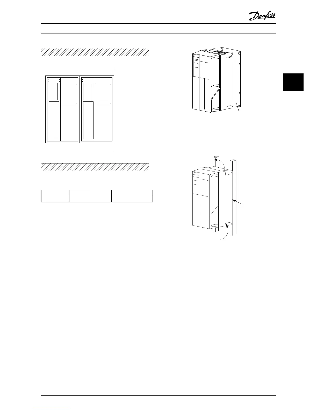
Illustration 2.1 Top and Bottom Cooling Clearance
Enclosure A2-A5 B1-B4 C1, C3 C2, C4
a/b [mm] 100 200 200 225
Table 2.1 Minimum Airflow Clearance Requirements
2.3.2 Lifting
•
Check
the weight of
the unit to determine a safe
lifting method
•
Ensure that the lifting device is suitable for the
task
•
If necessary, plan for a hoist, crane, or forklift with
the appropriate rating to move the unit
•
For lifting, use hoist rings on the unit, when
provided
2.3.3 Mounting
•
Mount
the
unit
vertically
•
The
frequency converter allows side by side
installation
•
Ensure that the strength of the mounting location
will support the unit weight
•
Mount the unit to a solid flat surface or to the
optional back plate to provide cooling airflow
(see Illustration 2.2 and Illustration 2.3)
•
Improper mounting can result in over heating
and reduced performance
•
Use the slotted mounting holes on the unit for
wall mounting, when provided
Illustration 2.2 Proper Mounting with Back Plate
Item
A
is
a
back plate properly installed for required
airflow to cool the unit.
Illustration 2.3 Proper Mounting with Railings
NOTE
Back plate is needed
when mounted on railings.
2.3.4 Tightening Torques
See 10.4 Connection Tightening Torques for proper
tightening specifications.
Installation
VLT
®
HVAC Drive Operating Instructions
MG11AI02 - VLT
®
is a registered Danfoss trademark
9
2 2