See 6 Application Set-Up Examples for typical control wiring
connections.
2
1
10 mm
130BA310.10
12 13
18
19
27
29
32
33
Illustration 2.21 Connecting Control Wiring
2.4.5.4 Using Screened Control Cables
Correct screening
The preferred method in
most cases is to secure control
and serial communication cables with screening clamps
provided at both ends to ensure best possible high
frequency cable contact.
If the earth potential between the frequency converter and
the PLC is different, electric noise may occur that will
disturb the entire system. Solve this problem by fitting an
equalizing cable next to the control cable. Minimum cable
cross section: 16 mm
2
.
1
2
PE
FC
PE
PLC
130BB922.11
PE PE
Illustration 2.22 Correct Screening
1
Min. 16 mm
2
2 Equalizing cable
Table 2.5 Legend to Illustration 2.22
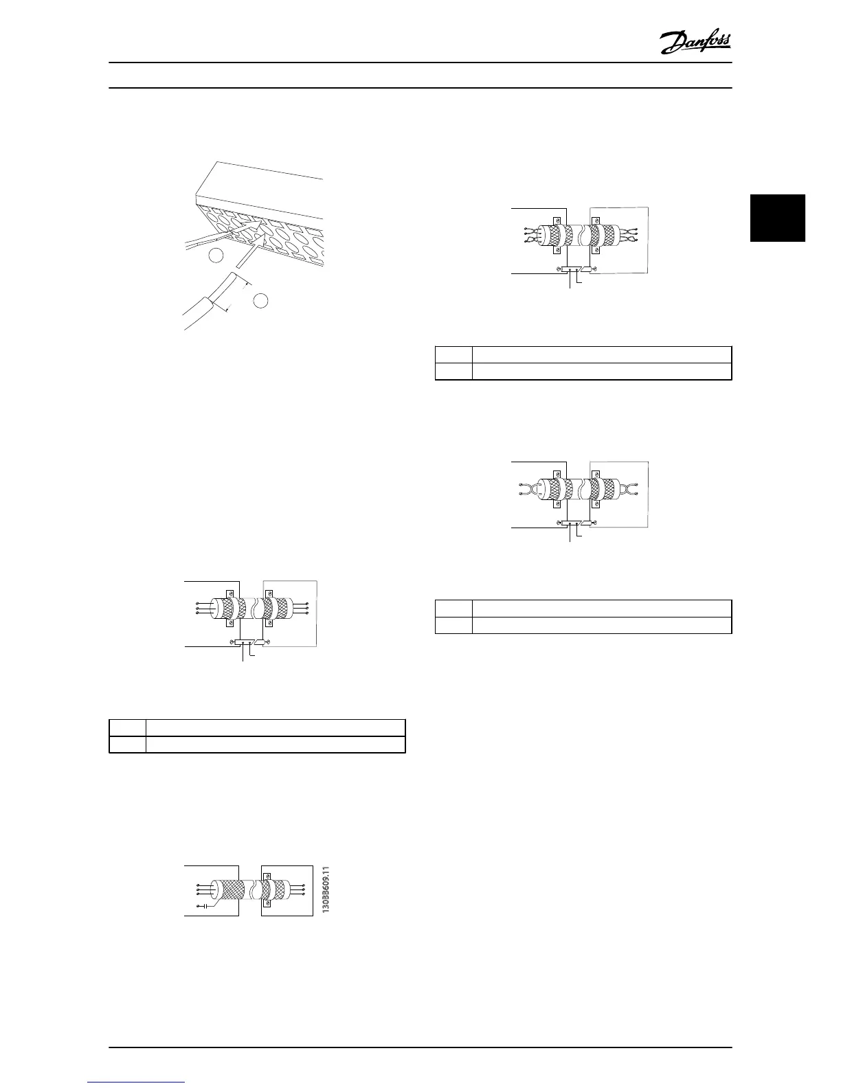
50/60 Hz ground
loops
With very long control cables, ground loops may occur. To
eliminate ground loops, connect one end of the screen-to-
ground with a 100 nF capacitor (keeping leads short).
100nF
FC
PE
PE
PLC
130BB609.11
Illustration 2.23 50/60 Hz Ground Loops
Avoid EMC noise on serial communication
This
terminal
is
connected
to earth via an internal RC link.
Use twisted-pair cables to reduce interference between
conductors. The recommended method is in
Illustration 2.24:
PE
FC
PE
FC
130BB923.11
PE PE
69
68
61
69
68
61
1
2
Illustration 2.24 Twisted-pair Cables
1
Min. 16 mm
2
2 Equalizing cable
Table 2.6 Legend to Illustration 2.24
Alternatively, the connection
to terminal 61 can be
omitted:
PE
FC
PE
FC
130BB924.11
PE PE
69
69
68
68
1
2
Illustration 2.25 Twisted-pair Cables without Terminal 61
1
Min. 16 mm
2
2 Equalizing cable
Table 2.7 Legend to Illustration 2.25
2.4.5.5 Control Terminal
Functions
Frequency converter functions are commanded by
receiving
control
input
signals.
•
Each terminal must be programmed for the
function it will be supporting in the parameters
associated with that terminal. See Table 2.4 for
terminals and associated parameters.
•
It is important to confirm that the control
terminal is programmed for the correct function.
See 4 User Interface for details on accessing
parameters and 5 About Frequency Converter
Programming for details on programming.
•
The default terminal programming is intended to
initiate frequency converter functioning in a
typical operational mode.
Installation
VLT
®
HVAC Drive Operating Instructions
MG11AI02 - VLT
®
is a registered Danfoss trademark
19
2 2
Phone: 800.894.0412 - Fax: 888.723.4773 - Web: www.ctiautomation.net - Email: info@ctiautomation.net