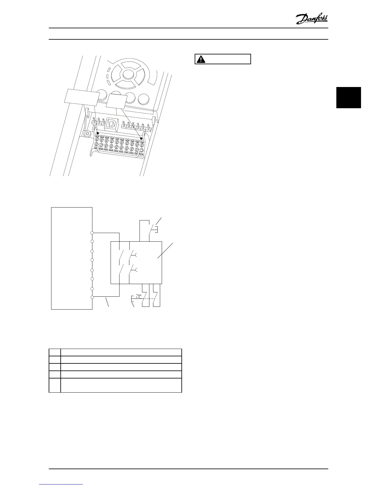
Illustration 2.28 Installation to Achieve a Stopping Category 0
(EN 60204-1) with
Cat. 3 /PL “d” (ISO 13849-1) or SIL 2 (EN
62061).
1 Frequency converter
2 [Reset] key
3 Safety relay (cat. 3, PL d or SIL2
4 Emergency stop button
5 Short-circuit protected cable (if not inside installation IP54
cabinet)
Table 2.9 Legend to Illustration
2.28
Safe
Stop
Commissioning Test
After installation and before first operation, perform a
commissioning test of the installation using safe stop.
Moreover, perform the test after each modification of the
installation.
WARNING
Safe Stop activation (that is removal of 24 V DC voltage
supply to terminal
37) does not provide electrical safety.
The Safe Stop function itself is therefore not sufficient to
implement the Emergency-Off function as defined by EN
60204-1. Emergency-Off requires measures of electrical
isolation, for example, by switching off mains via an
additional contactor.
1. Activate the Safe Stop function by removing the
24 V DC
voltage supply to the terminal 37.
2. After activation of Safe Stop (that is, after the
response time), the frequency converter coasts
(stops creating a rotational field in the motor).
The response time is typically less than 10 ms.
The frequency converter is guaranteed not to restart
creation of a rotational field by an internal fault (in
accordance with Cat. 3 PL d acc. EN ISO 13849-1 and SIL 2
acc. EN 62061). After activation of Safe Stop, the display
shows the text ”Safe Stop activated”. The associated help
text says, "Safe Stop has been activated”. This means that
the Safe Stop has been activated, or that normal operation
has not been resumed yet after Safe Stop activation.
NOTE
The requirements of
Cat. 3 /PL “d” (ISO 13849-1) are only
fulfilled while 24 V DC supply to terminal 37 is kept
removed or low by a safety device which itself fulfills Cat.
3 PL “d” (ISO 13849-1). If external forces act on the motor,
it must not operate without additional measures for fall
protection. External forces can arise for example, in the
event of vertical axis (suspended loads) where an
unwanted movement, for example caused by gravity, could
cause a hazard. Fall protection measures can be additional
mechanical brakes.
By default the Safe Stop function is set to an Unintended
Restart Prevention behaviour.
Therefore, to resume
operation after activation of Safe Stop,
1. reapply 24 V DC voltage to terminal 37 (text Safe
Stop activated is still displayed)
2. create a reset signal (via bus, Digital I/O, or
[Reset] key.
The Safe Stop function can be set to an Automatic Restart
behaviour. Set the value of 5-19 Terminal 37 Safe Stop from
default value [1] to value [3].
Automatic Restart means that Safe Stop is terminated, and
normal operation is resumed, as soon as the 24 V DC are
applied to Terminal 37. No Reset signal is required.
Installation
VLT
®
HVAC Drive Operating Instructions
MG11AI02 - VLT
®
is a registered Danfoss trademark
23
2 2