EasyManuals Logo

Danfoss 102 User Manual

Danfoss 102
94 pages
To Next Page IconTo Next Page
To Previous Page IconTo Previous Page
Page #9 background imageLoading...
Page #9 background image
1
2
3
4
5
6
7
8
9
10
11
12
13
16
17
18
19
14
15
FAN MOUNTING
QDF-30
DC-
DC+
Remove jumper to activate Safe Stop
Max. 24 Volt !
12
13
18
19 27 29 32
33
20
61
68
39
42
50
53 54
06 05 04
03 02 01
130BB493.10
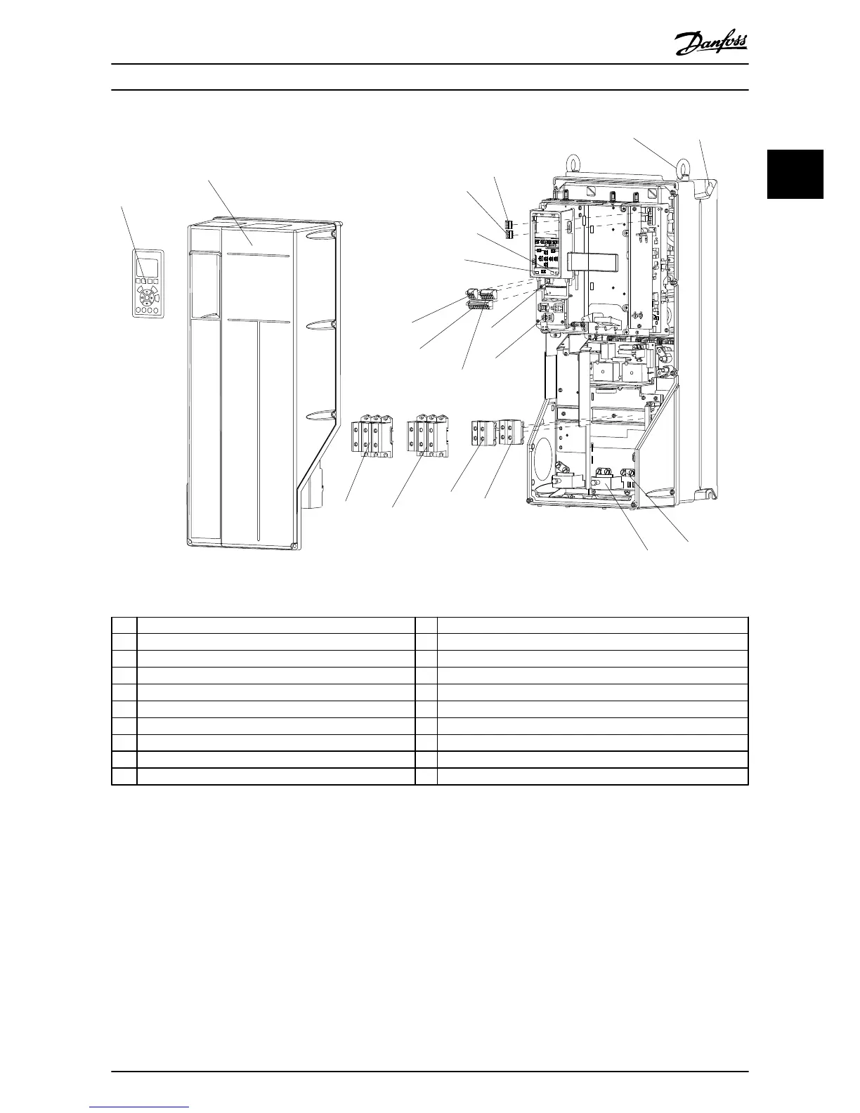
Illustration 1.2 Exploded View B and C Sizes
1 LCP 11 Relay 2 (04, 05, 06)
2 Cover 12 Lifting ring
3 RS-485 serial bus connector 13 Mounting slot
4 Digital I/O and 24 V power supply 14 Grounding clamp (PE)
5 Analog I/O connector 15 Cable strain relief / PE ground
6 Cable strain relief/PE ground 16 Brake terminal (-81, +82)
7 USB connector 17 Load sharing terminal (DC bus) (-88, +89)
8 Serial bus terminal switch 18 Motor output terminals 96 (U), 97 (V), 98 (W)
9 Analog switches (A53), (A54) 19 Mains input terminals 91 (L1), 92 (L2), 93 (L3)
10 Relay 1 (01, 02, 03)
Table 1.2 Legend to Illustration 1.2
Introduction
VLT
®
HVAC Drive Operating Instructions
MG11AI02 - VLT
®
is a registered Danfoss trademark
5
1 1
Phone: 800.894.0412 - Fax: 888.723.4773 - Web: www.ctiautomation.net - Email: info@ctiautomation.net

Table of Contents

Other manuals for Danfoss 102

Questions and Answers:

Question and Answer IconNeed help?

Do you have a question about the Danfoss 102 and is the answer not in the manual?

Danfoss 102 Specifications

General IconGeneral
Model102
MountingDIN rail
Operating temperature+70°C
Storage Temperature-40°C to +85°C
Humidity5% to 95% (non-condensing)
Number of ports1

Related product manuals