Dual compressors (Application 3 and 4)
Two compressor steps can be controlled cyclic or sequentially. At cyclic control, the two compressors must be of the
same size, while in sequential control compressor step 1 can be larger than step 2.
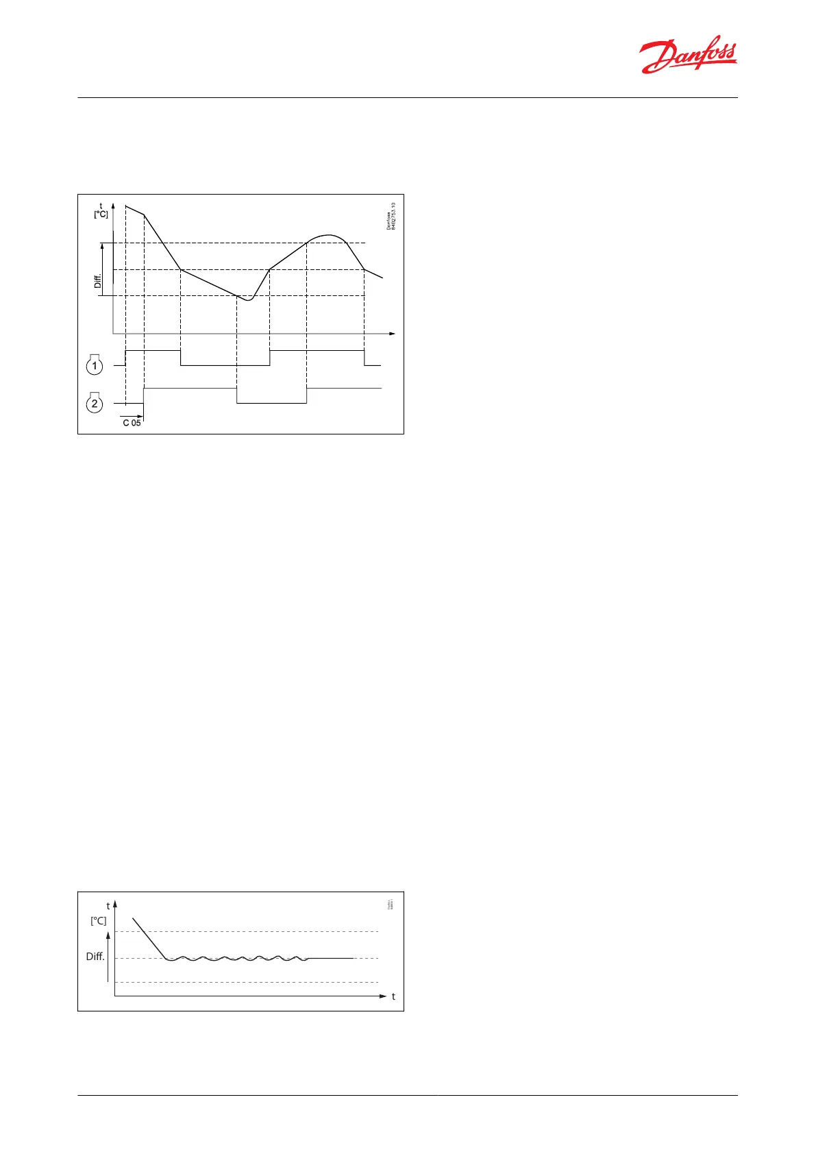
Figure 15: Control of two compressors
Cyclic control
When the controller demands refrigeration, it will rst cut in the compressor with the shortest operating time. After
the time delay, the second compressor will be cut in.
When the temperature has dropped to ”the middle of the dierential”, the compressor with the longest operation
time will be cut out. The running compressor will continue until the temperature has reached the cut-out value.
Then it will cut out.
When the temperature again reaches the middle of the dierential, a compressor will again be started. If one
compressor cannot maintain the temperature within the dierential, the second compressor will also be started.
If one of the compressors has run on its own for two hours, the compressors will be changed over so that
operational time is balanced. The two compressors must be of a type that can start up against a high pressure.
Sequential control
Compressor steps are controlled in the same manner as described for cyclic control, but compressor step 1 will
always be started rst and cut out as the last one. No time equalization is available in sequential control mode.
Variable speed compressor/pump (Application 5/6 and application 7/8)
Here the compressor/pump will be started when the controller requests cooling.
The analogue output signal will then be used to control the speed so that the temperature is kept very accurate at
the reference. The PI controller will automatically adapt the amplication, depending on how far the thermostat air
temperature is from the actual set reference temperature and thereby ensure fast pull-down when needed and
precise control when close to the reference temperature.
The actual reference is placed in the middle of the cut-out and cut-in temperatures (cut-out + ½ di).
Figure 16: Temperature variable
Diff.
[°C]
t
t
Danfoss
84B8301
To eliminate overshoot/undershoot at high load changes, the rate of change in speed can be limited via a max.
slope setting, which denes the maximum allowed change in speed per second (%/s).
AK-CC55 Water Loop
© Danfoss | Climate Solutions | 2022.04 BC378540472015en-000101 | 12