Danfoss
84B8316
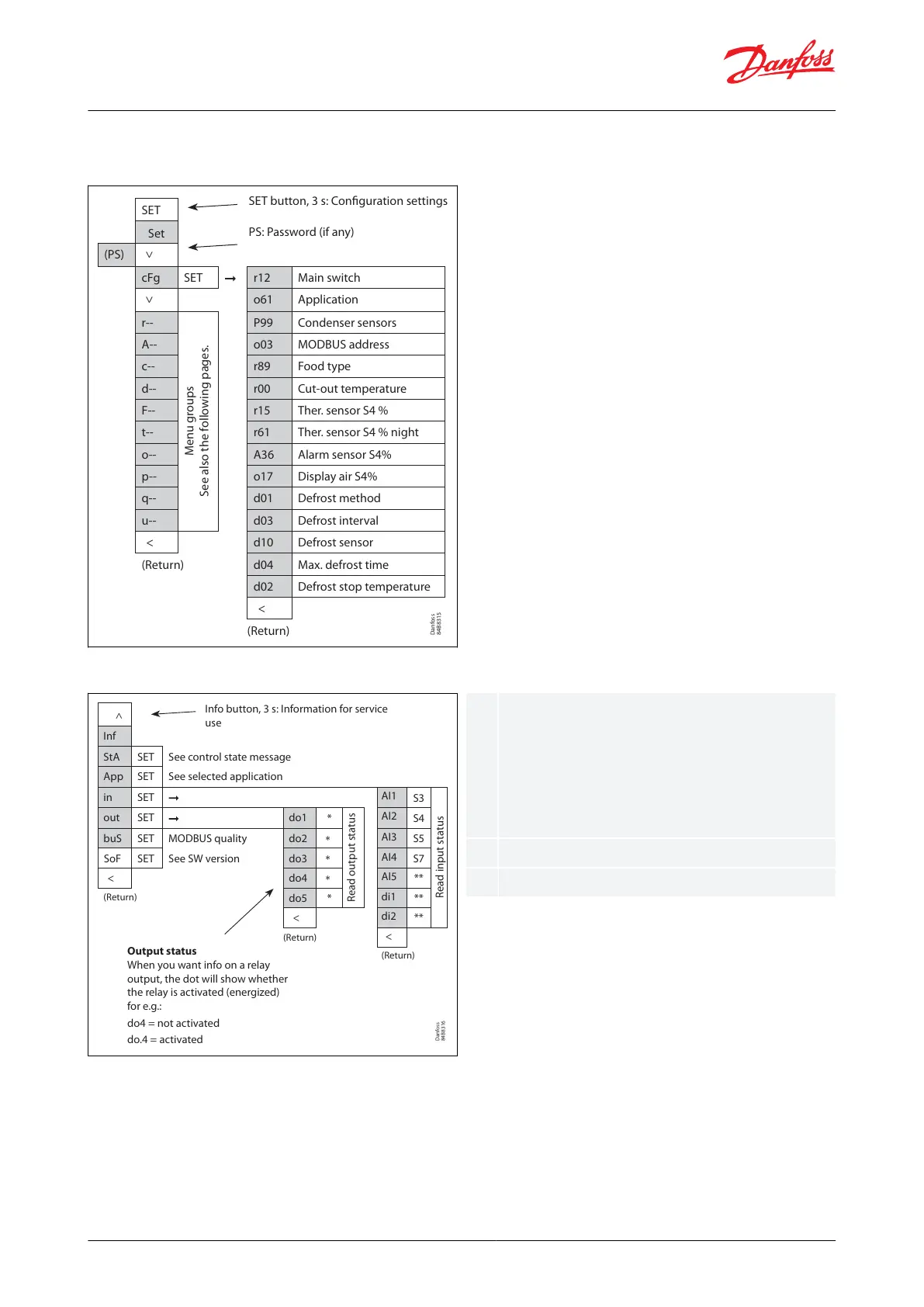
<
Inf
StA SET See control state message
App SET See selected application
in SET
AI1
S3
Read input status
out SET do1
*
Read output status
AI2
S4
buS SET MODBUS quality do2
*
AI3
S5
SoF SET See SW version do3
*
AI4
S7
< do4
*
AI5
**
(Return)
do5 *
di1
**
<
di2
**
(Return)
<
(Return)
Info button, 3 s: Information for service
use
Output status
When you want info on a relay
output, the dot will show whether
the relay is activated (energized)
for e.g.:
do4 = not activated
do.4 = activated
The output's function (determined at
conguration). DOs and AOs can also be forced
controlled from this menu, when r12 Main switch
has been set to position "service". Forced control of
a function can also be performed in codes q12 to
q50.
The input's function (determined at conguration)
See control state message in Table 38
1.
2.
3.
4.
Parameter groups when operating via display
Figure 57: SET button parameter list
Danfoss
84B8315
SET
Set
(PS)
<
cFg SET r12 Main switch
<
o61 Application
r--
Menu groups
See also the following pages.
P99 Condenser sensors
A-- o03 MODBUS address
c-- r89 Food type
d-- r00 Cut-out temperature
F-- r15 Ther. sensor S4 %
t-- r61 Ther. sensor S4 % night
o-- A36 Alarm sensor S4%
p-- o17 Display air S4%
q-- d01 Defrost method
u-- d03 Defrost interval
< d10 Defrost sensor
(Return) d04 Max. defrost time
d02 Defrost stop temperature
<
(Return)
SET button, 3 s: Configuration settings
PS: Password (if any)
Figure 58: Info button parameter list
Get a good start
With the following procedure you can start regulation very quickly:
Open parameter r12 and stop the regulation (in a new and not previously set unit, r12 will already be set to 0
which means stopped regulation.)
Select application based on the Wiring diagram
Open parameter o61 and set the application number
Select whether to use one or two temperature sensors for the water cooled condenser
AK-CC55 Water Loop
© Danfoss | Climate Solutions | 2022.04 BC378540472015en-000101 | 38