= Optional use
Table 10: Sensor description
Discharge air temperature
Return air temperature on second cooling section
Evaporator temperature on second evaporator
Table 11: Application with digital and analogue output specication
= Optional use
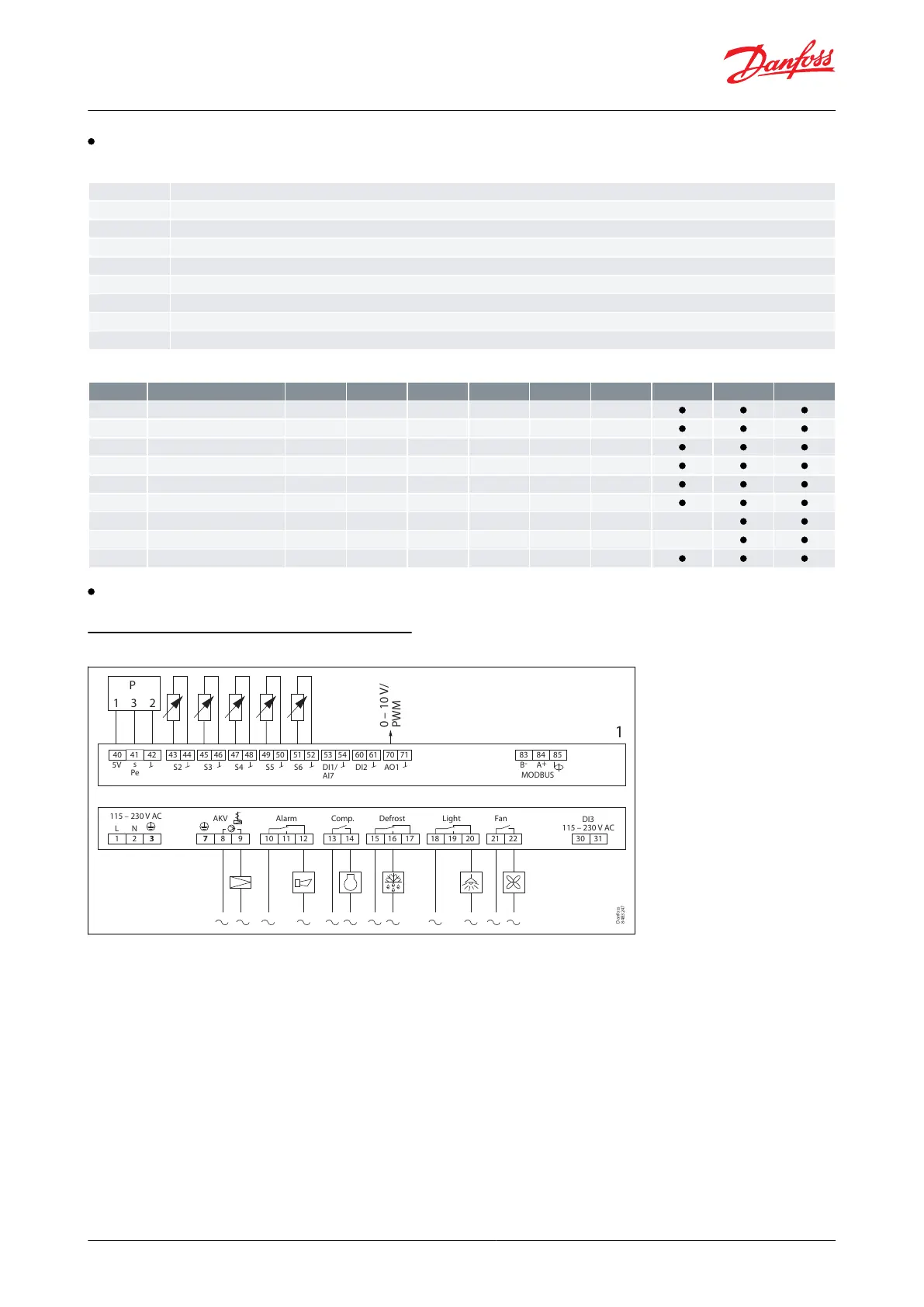
Application set-ups and IO connections
Figure 26: Connections for application 1
115 – 230 V AC
AKV Alarm Comp. Defrost Light Fan
DI3
115 – 230 V AC
1 2 3 7 8 9 10 11 12 13 14 21 22 30 3115 16 17 18 19 20
L N
40
5V
s
Pe
0 – 10 V/
PWM
S2 S3 S4 S5 S6 DI1/
AI7
DI2 AO1
1
41 42 43 44 45 46 47 48 49 50 51 52 53 54 60 61 70 71 83 84
B
-
A
+
MODBUS
85
P
1 3 2
Danfoss
84B3247
© Danfoss | Climate Solutions | 2021.02 BC364229688105en-000101 | 25
AK-CC55 Single Coil and Single Coil UI