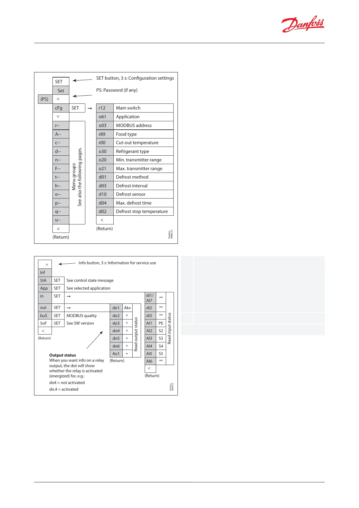
Figure 43: SET button parameter list
SET
Set
(PS)
<
cFg SET r12 Main switch
<
o61 Application
r-- o03 MODBUS address
A--
Menu groups
See also the following pages.
r89 Food type
c-- r00 Cut-out temperature
d-- o30 Refrigerant type
n-- o20 Min. transmitter range
F-- o21 Max. transmitter range
t-- d01 Defrost method
h-- d03 Defrost interval
o-- d10 Defrost sensor
p-- d04 Max. defrost time
q-- d02 Defrost stop temperature
u-- <
< (Return)
(Return)
SET button, 3 s: Configuration settings
PS: Password (if any)
Danfoss
84B8272
Danfoss
84B8279
Info button, 3 s: Information for service use
<
Inf
StA SET See control state message
App SET See selected application
in SET
di1/
AI7
**
Read input status
out SET
do1 Akv
Read output status
di2 **
buS SET MODBUS quality do2
*
di3 **
SoF SET See SW version do3
*
AI1 PE
< do4
*
AI2 S2
(Return)
do5
*
AI3 S3
do6
*
AI4 S4
AI5 S5
Ao1
*
AI6 **
(Return)
<
(Return)
Output status
When you want info on a relay
output, the dot will show
whether the relay is activated
(energized) for, e.g.:
do4 = not activated
do.4 = activated
The output's function (determined at
conguration). The DOs and AOs can also be
forced controlled from this menu, when r12 Main
switch has been set in position "service". Forced
control of a function can also be performed in
codes q11 to q27.
The input's function (determined at conguration).
See control state message in Table 49
1.
2.
3.
4.
5.
Parameter groups when operating via display
Figure 44: Info button parameter list
Get a good start
With the following procedure you can start regulation very quickly:
Open parameter r12 and stop the regulation (in a new and not previously set unit, r12 will already be set to 0
which means stopped regulation)
Select application based on the wiring diagrams on Page 25
Open parameter o61 and set the application number
For network. Set the address in o03
Then select a set of presets from the "Food type" help table
© Danfoss | Climate Solutions | 2021.02 BC364229688105en-000101 | 37
AK-CC55 Single Coil and Single Coil UI