Master control signal used to shut down a case for a
time period. During shutdown there will be no alarm
monitoring
Master control signal that will close the injection
valve
Master control signal that will provide forced cooling
Master control signal for starting a defrost. At adap-
tive defrost the defrost might be skipped if the de-
frost is not needed
Read out the actual state of the defrost
Master control signal used for co-ordinated defrost
control to hold cabinets from returning to normal re-
frigeration after a defrost until all cabinets have termi-
nated defrost
Master control signal used to prevent a defrost start
in a controller.
Master control signal used by system manager to see
if a controller is requesting that the next defrost has
to be carried out
Master control signal for control of light via a data
communication signal from the system manager
Master control signal sending the actual measured
dewpoint from the system manager to the controller
over the network.
Master control signal distributing the condensing
temperature signal to the case controllers that are us-
ing adaptive defrost. At transcritical CO2 sites the re-
ceiver pressure is distributed to the case controllers.
This function needs to be set up in the system man-
ager.
Master control signal that will lock down all Bluetooth
data communication
Required minimum delta temperature across evapo-
rator (S3 - Te) in order to keep the air temperature at
the actual setpoint
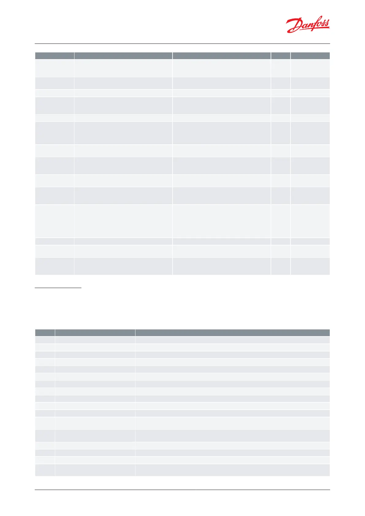
Fault message
In an error situation the alarm LED on the front will be on and the alarm relay will be activated (depending on
priority). If you push the alarm button for 3 seconds you can see the alarm report in the display. (Alarm priorities can
be changed. See Table 40: Alarm relay priorities.) Here are the messages that may appear:
Table 48: Fault message
The controller has a hardware failure
Clock has lost valid time
Pe Evap. pressure A - Sensor error
Sensor signal is out of range. Please check the sensor for correct operation
S2 Gas outlet A - Sensor error
Sensor signal is out of range. Please check the sensor for correct operation
S3 Air ON evap. A - Sensor error
Sensor signal is out of range. Please check the sensor for correct operation
S4 Air OFF evap. A - Sensor error
Sensor signal is out of range. Please check the sensor for correct operation
S5 Evaporator A - Sensor error
Sensor signal is out of range. Please check the sensor for correct operation
S6 product temp. A - Sensor error
Sensor signal is out of range. Please check the sensor for correct operation
S3 Air ON evap. B - Sensor error
Sensor signal is out of range. Please check the sensor for correct operation
S5 Evaporator B - Sensor error
Sensor signal is out of range. Please check the sensor for correct operation
Humidity sensor - Sensor error
Sensor signal is out of range. Please check the sensor for correct operation
The alarm temperature has been above the max alarm limit for a longer time period than the set alarm de-
lay.
The alarm temperature has been below the min alarm limit for a longer time period than the set alarm de-
lay.
The door has been open for a too long time
Max defrost hold time exceeded
The controller has been waiting longer time than permitted after a co-ordinated defrost.
The refrigerant has not been selected hence control can not be initiated
S6 high product temperature A
The S6 Product temperature has been above the max alarm limit for a longer time period than the set alarm
delay.
AK-CC55 Single Coil and Single Coil UI
© Danfoss | Climate Solutions | 2021.02 BC364229688105en-000101 | 62