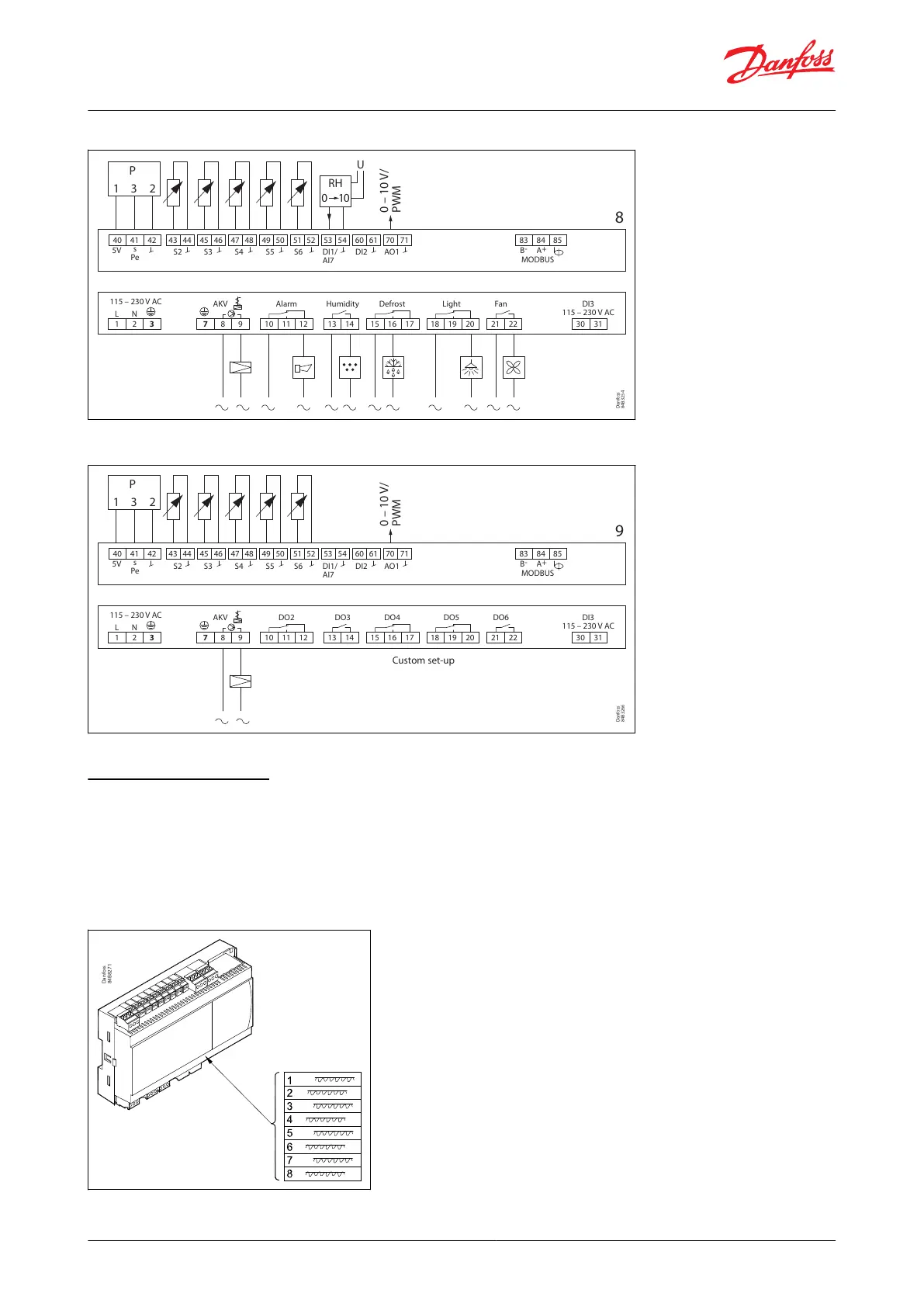
Figure 33: Connections for application 8
115 – 230 V AC
AKV Alarm Humidity Defrost Light Fan
DI3
115 – 230 V AC
1 2 3 7 8 9 10 11 12 13 14 21 22 30 3115 16 17 18 19 20
L N
40
5V
s
Pe
0 – 10 V/
PWM
S2 S3 S4 S5 S6 DI2 AO1
8
41 42 43 44 45 46 47 48 49 50 51 52 53 54 60 61 70 71 83 84
B
-
A
+
MODBUS
85
P
1 3 2
RH
U
0 10
Danfoss
84B3254
DI1/
AI7
Figure 34: Connections for application 9
115 – 230 V AC
AKV DO2 DO3 DO4
Custom set-up
DO5 DO6
DI3
115 – 230 V AC
1 2 3 7 8 9 10 11 12 13 14 21 22 30 3115 16 17 18 19 20
L N
40
5V
s
Pe
0 – 10 V/
PWM
S2 S3 S4 S5 S6 DI2 AO1
9
41 42 43 44 45 46 47 48 49 50 51 52 53 54 60 61 70 71 83 84
B
-
A
+
MODBUS
85
P
1 3 2
Danfoss
84B3266
DI1/
AI7
Product identication
The controller is provided with labels from the factory, indicating a generic application. When selecting the required
application, specic labels are provided so that you can mount the relevant one.
The application number is indicated on the left-hand side of the labels. Use the label tting the selected application.
Some of the labels are applicable to multiple application options.
Figure 35: Product identication
AK-CC55 Single Coil and Single Coil UI
© Danfoss | Climate Solutions | 2021.02 BC364229688105en-000101 | 28