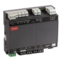
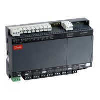
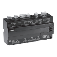
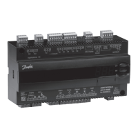
Connection of normally closed valve in connection with stepper valve.
DO2
• Alarm
There is a connection between terminal 10 and 12 in alarm situations and when the controller is without power.
DO2 has reinforced insulation that can be used with 24 V.
• Light, Rail heat, Compressor, Night blind
There is connection between terminal 10 and 11 (10 and 12 at light) when the function is on.
• Suction line valve
There is connection between terminal 10 and 11 when the suction line must be open.
DO3
• Compressor, Rail heat, Defrost, Drain valve, Humidity
There is connection between terminal 13 and 14 when the function must be active.
DO4
• Defrost
There is connection between terminal 15 and 16 when defrosting takes place.
• Hot gas
There is connection between terminal 15 and 16 when the hot gas valves must open.
NOTE:
When replacing AK-CC 550 with AK-CC55, wires must be switched.
DO5
• Light
There is connection between terminal 18 and 20 when the function must be active.
• Rail heat
There is connection between terminal 18 and 19 when the rail heat must be on.
DO6
• Fan
There is connection between terminal 21 and 22 when the fan is on.
DO2-DO6 + AO1 and Application 9
Here, the dierent outputs can be custom dened in q02-q09
DI3
Digital input signal
The signal must have a voltage of 0 / 230 V AC (115 V AC)
The function is dened in o84.
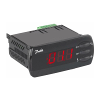
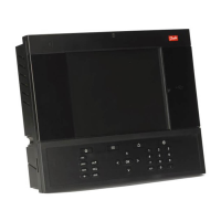
Display (RJ12 plug)
If external readings/operation of the controller is required, a display can be connected. If there is no display on the
front, two external displays can be connected. For one display the max. cable length is 100 m. For two displays the
sum of the two cable lengths must not exceed 100 m.
NOTE:
When replacing AK-CC 550 with AK-CC55, AKA 16X remote displays and cables have to be replaced with new AK-
UI55 displays and cables.
Electric noise
Cables for sensors, low voltage DI inputs and data communication must be kept separate from other high voltage
cables:
• Use separate cable trays
• Keep a distance between cables of at least 10 cm
• Long cables at the low voltage DI input should be avoided
Installation considerations
Accidental damage, poor installation, or site conditions, can give rise to malfunctions of the control system, and
ultimately lead to a plant breakdown.
AK-CC55 Single Coil and Single Coil UI
© Danfoss | Climate Solutions | 2021.02 BC364229688105en-000101 | 32
 Loading...
