m2 Version 3.11 Manual RS.8A.N5.02 © Danfoss 10-2007 19
Input Type
Input Number
Y Axis
Y Base
4 - 20 mA Inputs
Use the ‘ ’ or ‘ ’ keys to cycle through the character list to the required value
and the ‘ ’ or ‘ ’ key to move the cursor left or right respectively. Press the ‘↵’
key to move onto the next eld.
Use the ‘ ’and ‘ ’ keys to cycle through the valid options as follows:
· RESISTOR Resistor input.
· CURRENT 4 - 20 mA input.
· DIGITAL Normally open or normally closed contacts (Contact).
· PT1000 PT1000
This eld is to specify the input number of the (Remote) third party controller or
m2+ unit.
Use the ‘ ’ or ‘ ’ keys to cycle through the character list to the required value
and the ‘ ’ or ‘ ’ key to move the cursor left or right respectively. Press the ‘↵’
key to move onto the next eld.
This eld refers to the overall size of the graph temperature range. Entering
zero selects the auto-scale option. Alternatively, enter the required range. The
range goes from the lowest graph point (Y Base value) to the highest graph
point. Use the ‘ ’, ‘ ’, ‘ ’ or '‘ ’ keys to enter the required value.
This eld refers to the lowest value the graph will show. This value should be
slightly lower than you expect the temperature to drop to. If auto scale in the Y
axis is selected this value is not used. Use the ‘ ’, ‘ ’, ‘ ’ or '‘ ’ keys to enter
the required value.
These values are used exclusively in conjunction with a standard 4-20 mA input
which can represent pressure, humidity, level, ow rate, or any other variable
which can produce a 4-20 mA output.
The value for the upper and lower limits can therefore represent % (RH), PPM,
bar or psi etc., depending on the medium being measured. A numerical
value for 4 mA (lower limit) and 20 mA (higher limit) is entered, and the m2
automatically scales the input for a gure proportional to the measurement.
Use the ‘ ’, ‘ ’, ‘ ’ and ‘ ’ keys to enter the required value.
Finally, press ‘ ’ to return to the Setup Menu.
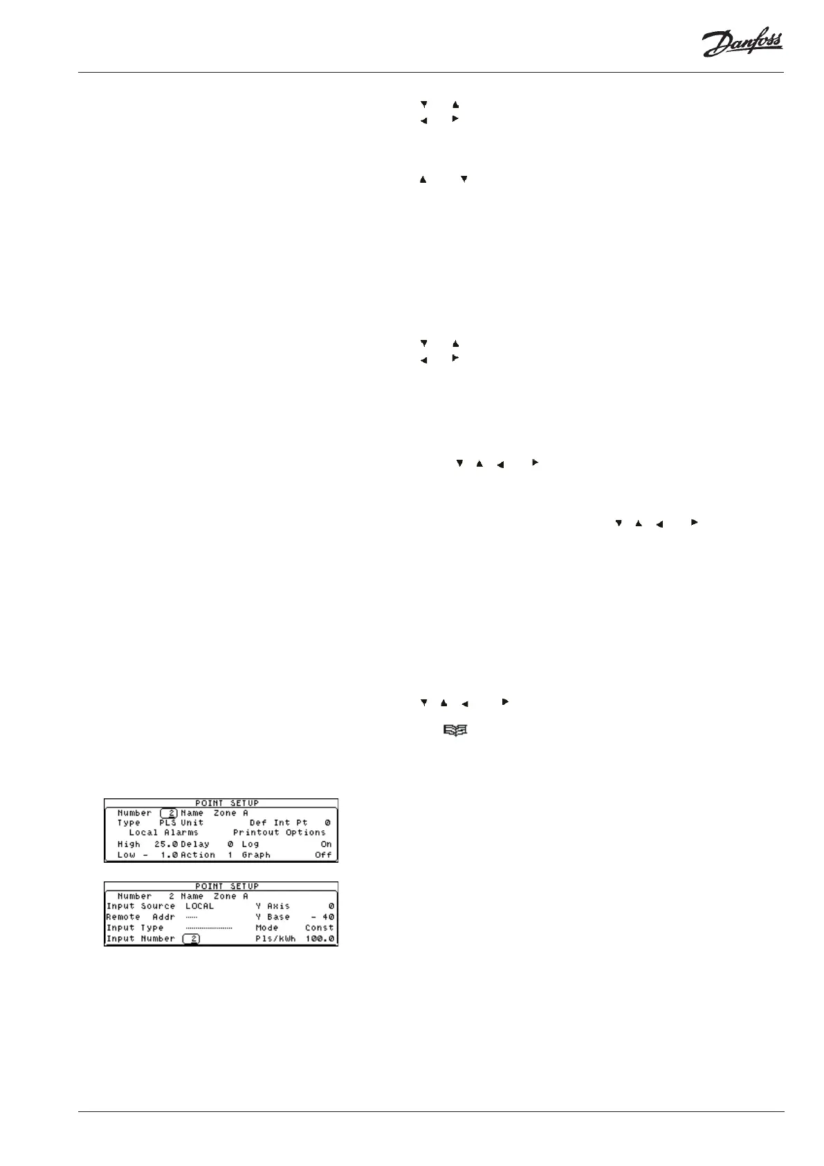
To setup the pulsed input, from the Point Setup menu select ‘PLS’ in the Point
Type eld. All the remaining elds in ‘Screen 1’ of the Point Setup are the same
as normal.
In ‘Screen 2’ of the Point Setup there are a couple of extra elds added. These
are as explained below:
This eld is to set either the ‘Constant’ or ‘Peak’ value to be used as explained
previously.
This eld is to set the amount of pulses that is to be recieved from the power
meter per kWh.
Pulsed Input Setup
Mode
Pls/kWh