m2 Version 3.11 Manual RS.8A.N5.02 © Danfoss 10-2007 31
EKC measurements and setup
Concept
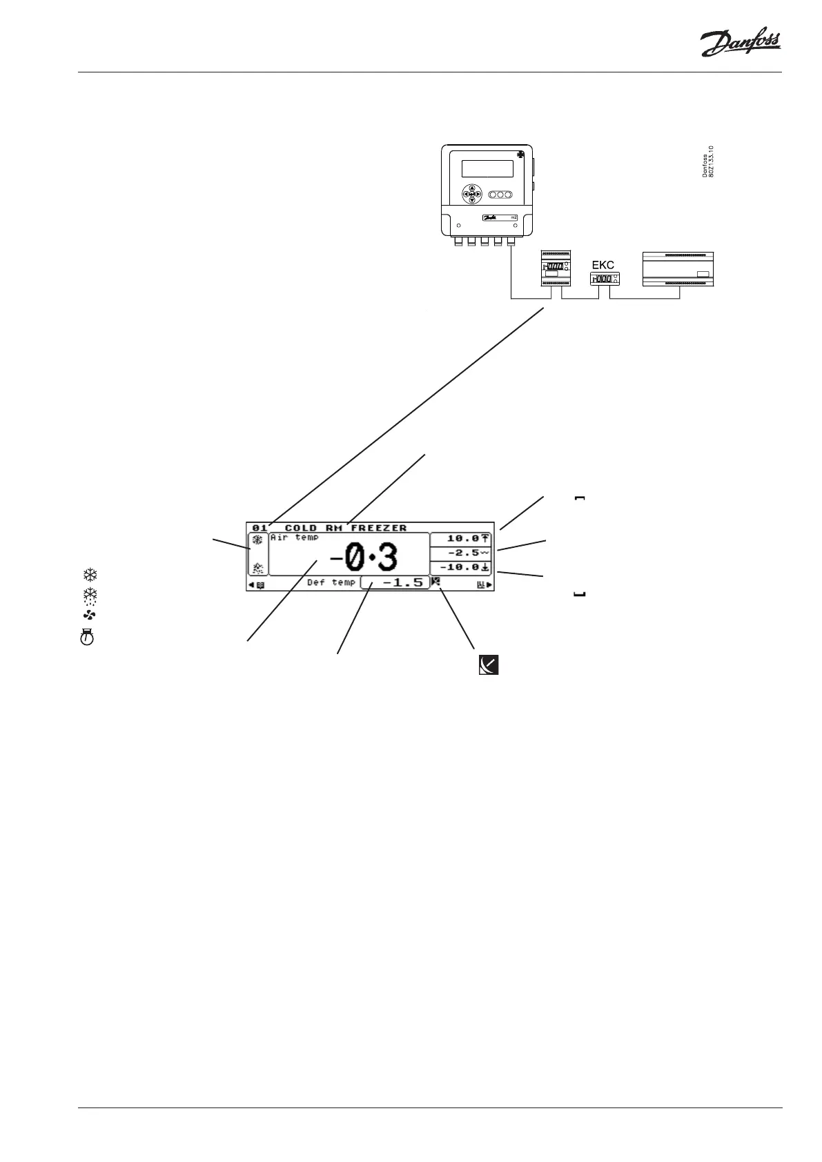
The m2 display can display data from individual
controllers. Data is uploaded to m2 via data com-
munication.
The following can be displayed, depending on the
type of controller and what is being regulated:
The point number will correspond to a controller address
Supplementary text that can
be added to the point number
Indicates the upper alarm limit setting. When
the of the symbol is scrolling, it indicates
that the upper alarm limit has been exceeded.
A wave
Indicates the set point for the EKC controller
Indicates the lower alarm limit setting. When
the part of the symbol is scrolling, it
indicates that the lower alarm limit has been
exceeded.
Primary meas-
urement from
the controller.
This shows the
air temperature.
For a pack con-
trol it could be:
P0 bar
- Remote - alarms are based on controller settings.
Alarm limits will be determined by the external controller.
Some alarm limits are set as absolute values, others as a
dierence to the set point. See controller data.
Regulation status is shown
by means of icons, e.g.:
- cooling
- defrost
- fans on
- compressors on
Secondary measure-
ment from the
controller.
This shows the de-
frost temperature.
For a pack control it
could be:
Pc bar