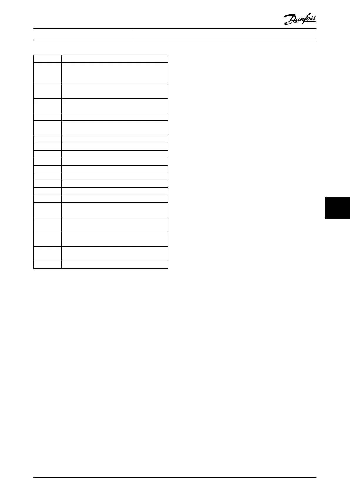
No. Text
2326 Power card configuration is determined to be
incorrect after the delay for power cards to
register.
2327 Too many power card locations have been
registered as present.
2330 Power size information between the power cards
does not match.
2561 No communication from DSP to ATACD.
2562 No communication from ATACD to DSP (state
running).
2816 Stack overflow control board module.
2817 Scheduler slow tasks.
2818 Fast tasks.
2819 Parameter thread.
2820 LCP stack overflow.
2821 Serial port overflow.
2822 USB port overflow.
2836 cfListMempool too small.
3072-5122 Parameter value is outside its limits.
5123 Option in slot A: Hardware incompatible with
control board hardware.
5124 Option in slot B: Hardware incompatible with
Control board hardware.
5125 Option in slot C0: Hardware incompatible with
control board hardware.
5126 Option in slot C1: Hardware incompatible with
control board hardware.
5376-6231 Out of memory.
Table 8.4 Code Numbers for Internal Faults
ALARM 39, Heat sink sensor
No feedback from the heat sink temperature sensor.
The signal from the IGBT thermal sensor is not available on
the power card. The problem could be on the power card,
on the gate drive card, or the ribbon cable between the
power card and gate drive card.
WARNING 40, Overload of digital output terminal 27
Check the load connected to terminal 27 or remove short-
circuit connection. Check 5-00 Digital I/O Mode and
parameter 5-01 Terminal 27 Mode.
WARNING 41, Overload of digital output terminal 29
Check the load connected to terminal 29 or remove short-
circuit connection. Check 5-00 Digital I/O Mode and
parameter 5-02 Terminal 29 Mode.
WARNING 42, Overload of digital output on X30/6 or
overload of digital output on X30/7
For X30/6, check the load connected to X30/6 or remove
the short-circuit connection. Check 5-32 Term X30/6 Digi
Out (MCB 101).
For X30/7, check the load connected to X30/7 or remove
the short-circuit connection. Check 5-33 Term X30/7 Digi
Out (MCB 101).
ALARM 46, Power card supply
The supply on the power card is out of range.
There are 3 power supplies generated by the switch mode
power supply (SMPS) on the power card: 24 V, 5 V, ±18 V.
When powered with 24 V DC with the MCB 107 option,
only the 24 V and 5 V supplies are monitored. When
powered with 3 phase mains voltage, all 3 supplies are
monitored.
WARNING 47, 24V supply low
The 24 V DC is measured on the control card. The external
24 V DC back-up power supply may be overloaded,
otherwise contact the Danfoss supplier.
WARNING 48, 1.8V supply low
The 1.8 V DC supply used on the control card is outside of
allowable limits. The power supply is measured on the
control card. Check for a defective control card. If an
option card is present, check for an overvoltage condition.
WARNING 49, Speed limit
When the speed is not within the specified range in
parameter 4-11 Motor Speed Low Limit [RPM] and
parameter 4-13 Motor Speed High Limit [RPM], the frequency
converter shows a warning. When the speed is below the
specified limit in 1-86 Trip Speed Low [RPM] (except when
starting or stopping) the frequency converter trips.
ALARM 50, AMA calibration failed
Contact the Danfoss supplier or Danfoss Service
Department.
ALARM 51, AMA check U
nom
and I
nom
The settings for motor voltage, motor current, and motor
power are wrong. Check the settings in parameters 1-20 to
1-25.
ALARM 52, AMA low I
nom
The motor current is too low. Check the settings.
ALARM 53, AMA motor too big
The motor is too big for the AMA to operate.
ALARM 54, AMA motor too small
The motor is too small for the AMA to operate.
ALARM 55, AMA parameter out of range
The parameter values of the motor are outside of the
acceptable range. AMA does not run.
ALARM 56, AMA interrupted by user
The user has interrupted the AMA.
ALARM 57, AMA internal fault
Try to restart AMA again a number of times, until the AMA
is carried out. Note that repeated runs may heat the motor
to a level where the resistance R
s
and R
r
are increased. In
most cases, however, this is not critical.
ALARM 58, AMA Internal fault
Contact the Danfoss supplier.
Warnings and Alarms
VLT HVAC Drive FC 102 Operating Instructions
MG11F402 - Rev. 2013-12-16 137
8 8
 Loading...


