1-80 Function at Stop
Option: Function:
Select the frequency converter function after a
stop command or after the speed is ramped
down to the settings in 1-81 Min Speed for
Function at Stop [RPM].
Available selections depend on 1-10 Motor
Construction:
[0] Asynchron:
[0] coast
[1] DC-hold
[2] Motor check, warning
[6] Motor check, alarm
[1] PM non salient:
[0] coast
[0] * Coast Leaves motor in free mode.
[1] DC Hold/
Motor
Preheat
Energizes motor with a DC holding current
(see parameter 2-00 DC Hold/Preheat Current).
[2] Motor
check,
warning
Issues a warning if the motor is not
connected.
[6] Motor
check,
alarm
Issues an alarm if the motor is not connected.
1-90 Motor Thermal Protection
Option: Function:
The frequency converter determines the
motor temperature for motor protection in 2
different ways:
•
Via a thermistor sensor connected
to one of the analog or digital
inputs (parameter 1-93 Thermistor
Source).
•
Via calculation (ETR = Electronic
Thermal Relay) of the thermal load,
based on the actual load and time.
The calculated thermal load is
comed with the rated motor current
I
M,N
and the rated motor frequency
f
M,N
. The calculations estimate the
need for a lower load at lower
speed due to less cooling from the
fan incorporated in the motor.
[0] No
protection
If the motor is continuously overloaded and
no warning or trip of frequency converter is
wanted.
[1] Thermistor
warning
Activates a warning when the connected
thermistor in the motor reacts in the event of
motor overtemperature.
1-90 Motor Thermal Protection
Option: Function:
[2] Thermistor
trip
Stops (trips) the frequency converter when
the connected thermistor in the motor reacts
in the event of motor over-temperature.
[3] ETR warning
1
[4] ETR trip 1
[5] ETR warning
2
[6] ETR trip 2
[7] ETR warning
3
[8] ETR trip 3
[9] ETR warning
4
[10] ETR trip 4
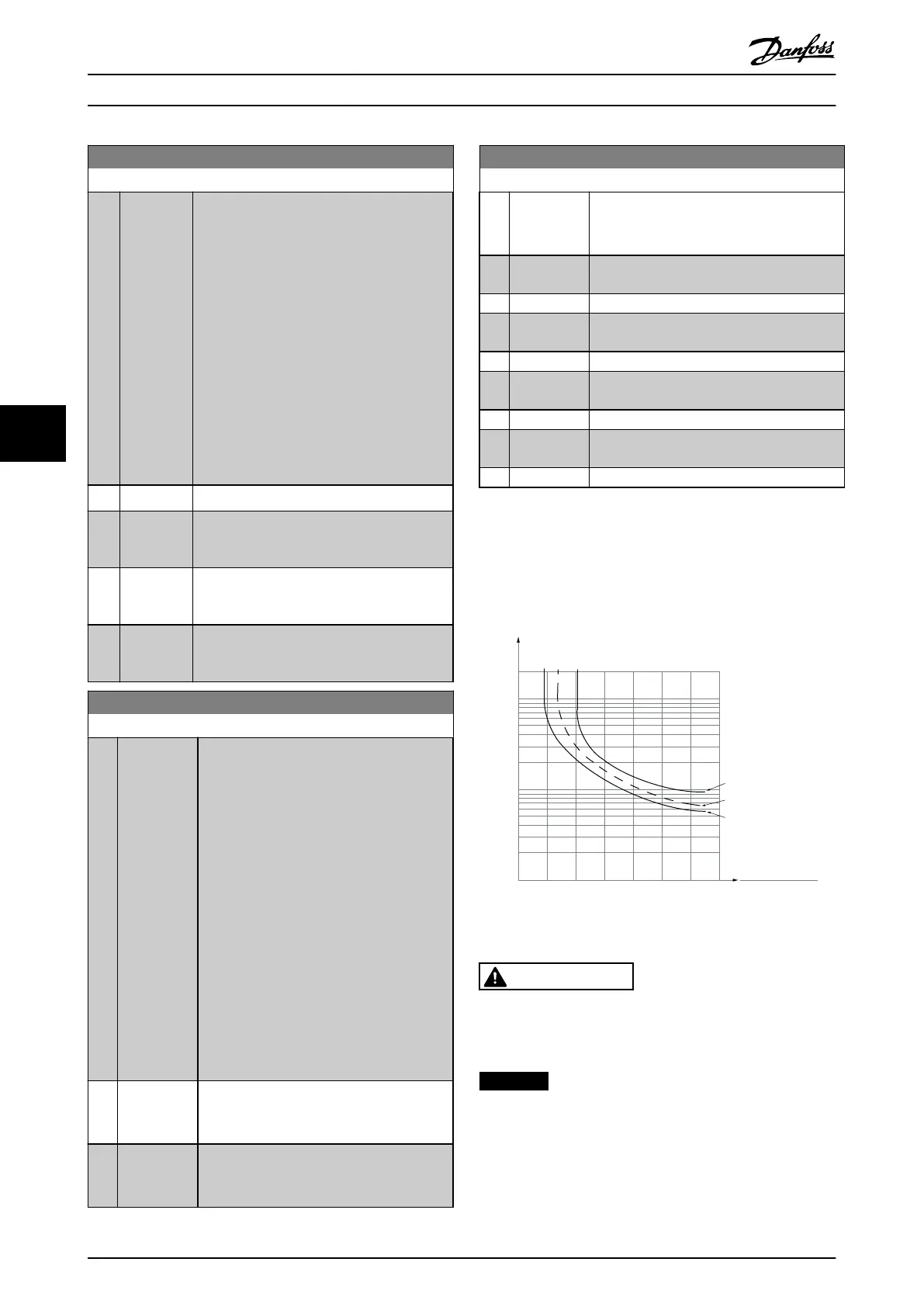
ETR (Electronic Thermal Relay) functions 1-4 calculates the
load when the set-up where they were selected is active.
For example ETR-3 starts calculating when set-up 3 is
selected. For the North American market: The ETR
functions provide class 20 motor overload protection in
accordance with NEC.
1.21.0 1.4
30
10
20
100
60
40
50
1.81.6 2.0
2000
500
200
400
300
1000
600
t [s]
175ZA052.12
f
OUT
= 2 x f
M,N
f
OUT
= 0.2 x f
M,N
f
OUT
= 1 x f
M,N
(par. 1-23)
I
MN
(par. 1-24)
I
M
Illustration 6.9
WARNING
To maintain PELV, all connections made to the control
terminals must be PELV, e.g. thermistor must be
reinforced/double insulated
NOTICE
Danfoss recommends using 24 V DC as thermistor supply
voltage.
How to Programme VLT HVAC Drive FC 102 Operating Instructions
94 MG11F402 - Rev. 2013-12-16
66
 Loading...


