46 | © Danfoss | August 2018 AQ00000211
The AD3 input has a fixed 20Hz low-pass filter and is not affected by P3249!
7.6.1.2 Analogue input drift compensation
A radiometric compensation algorithm has been implemented to ensure robustness of the analogue sensor signal either
from the wheel angle senor(s) or from an analogue joystick, even when the 5VDC sensor supply drifts between 4.65 –
5.35VDC. Checks are done between the calibrated sensor supplies (P3217 and P3219) and the actual 5VDC sensor
supply.
Danfoss recommends to activate the drift compensation for analogue sensors without built-in compensation.
The objective is to compensate for any drift in the analogue sensor values as a result of aging or temperature of the
electronic circuits.
To select compensation for the primary analogue sensor and, if present, the redundant analogue sensor, set the parameter
value for P3246 and P3247 both to 255.
If no compensation is needed set parameter P3246 and P3247 both to 0.
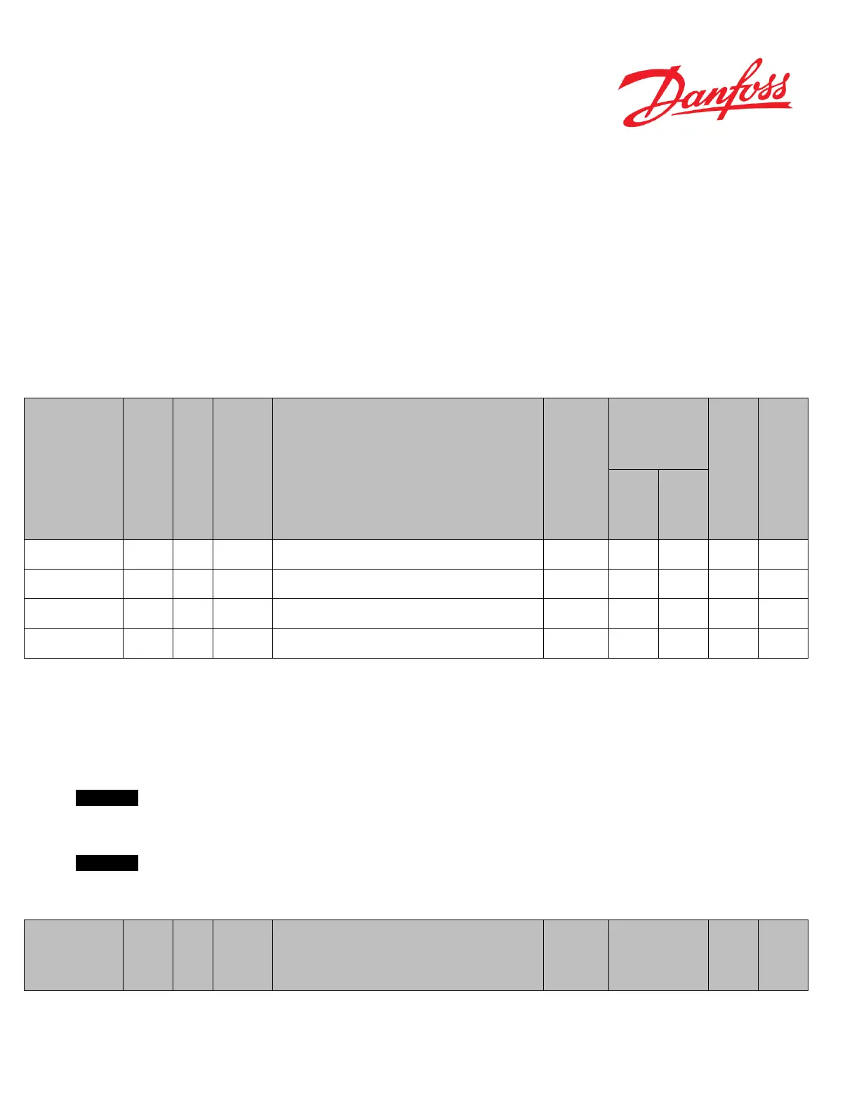
Name
Description of parameter
Range
default
Safety critical
parameters ‘S’
primary analogue sensor
P3217 U16 mVolts Measured Supply voltage during calibration of the primary analogue sensor OEM, Dealer 4650 5350 5000
redundant analogue
sensor during calibration
P3219 U16 mVolts
Measured Supply voltage during calibration of the redundant analogue
sensor
OEM, Dealer 4650 5350 5000
for Primary analogue
P3246 U8 -
Supply voltage compensation Enable/Disable for processing primary
Analogue sensor signal
Valid Values: 0 (DISABLE); 255 (ENABLE)
OEM 0 255 255
for Redundant analogue
P3247 U8 -
Supply voltage compensation Enable/Disable for processing redundant
analogue sensor signal
Valid Values: 0 (DISABLE); 255 (ENABLE)
OEM 0 255 255
Table 16
7.6.1.3 Sensor supply test
With P3248, the internal 5V supply on the PVED-CLS’ pin 11 can be enabled/disabled. This parameter is only intended
for testing purpose, and should be kept at Enable (P3248 set to 0) all time.
Important
P3248 set to 1 will shut down the sensor supply but not the monitoring of it. So if it is disabled (i.e. P3248 set to 1), an
external 5V supply has to be connected to PVED-CLS sensor supply pin (pin 11) else PVED-CLS will go to safe state.
Important
If an internal 5V is chosen in the PVED-CLS and a WAS of the potentiometer-type, remember to setup the analogue
channel compensation parameters too (P3246 and P3247).
Name
Description of parameter
Range