© Danfoss | August 2018 AQ00000211 | 91
Anti
-jerk
Base Anti-jerk algorithm
Anti-jerk on-the-top
For dampen STW speed
fluctuations
Flow command1
Flow command Flow command
Anti-jerk on-the-top
LPF
Average
Crossover
EEPROM parameters
STW Anti-jerk filter Cut-off
frequency (P3582)
STW Anti-jerk Cross-over start (P3578)
STW Anti-jerk Cross-over stop (P3580)
Flow command
Flow command1
Average flow command
Flow command
LPF flow command
Crossover
100%
0%
P3578 P3580
Factor LPF flov command
Factor flow command
|average flow command|
Out = Factor LPF flow command x LPF flow command + Factor flow command x flow command
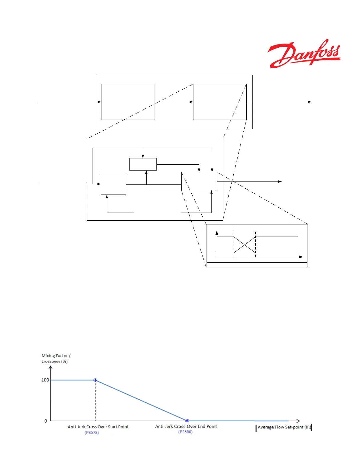
Figure 44
Referring to the Figure below, the ‘crossover/mixing factor’ in percentage is calculated and is applied on ‘Filtered flow
set-point’ (see 10.6.1) to calculate the final ‘flow set-point’ of Anti-jerk algorithm.
Parameters P3578 and P3580 are used to calculate the percentage crossover to be applied on the ‘filtered flow set-point’(see
10.6.1) to calculate the final ‘flow set-point’ with anti-jerk functionality.
The ‘Crossover/mixing factor’ is defined by the piece-wise linear characteristics based on following points in Figure 5.
The absolute value of average flow set-point is calculated from ‘Modified Flow Set-point’(see 10.6.1) and ‘Filtered Flow
Set-point’ (see 10.6.1) in IR.