Service Monitor User Manual
Danfoss Turbocor Compressors Inc. 27
ECD-00007M Rev. 1
NOTE:
In Manual Control mode, the Chiller Interface interlock
switch has no effect on the compressor state.
Analog Input
The Analog Input mode controls the compressor loading
using an analog demand signal of 0-10 VDC from an
external controller. The variable demand signal corresponds
to the range of 0-100% maximum power available.
NOTE:
The Chiller Interface interlock switch must be closed and
no errors present for the compressor to start up and run.
Modbus Network
In Modbus Network mode, the compressor receives a
demand from an external computer, PLC, or building
management system using the Modbus protocol on a RS-
232 or RS4-85 communication link.
In Modbus Network mode, the user may only set the
“Loading Demand (% max power)” parameter from the
“Compressor Controller” window. Refer to 6.3
"Compressor Control". All other parameters in the monitor
program may only be viewed.
NOTE:
The Chiller Interface interlock switch must be closed and
no errors present for the compressor to start up and run.
Chiller Control
The Chiller Control mode is fully automatic and controls
the chilled water or air temperature using a temperature
sensor connected directly to the Chiller Interface module.
This mode can also be used to control evaporating
temperature which is derived from the suction pressure
measurement.
NOTE:
The Chiller Interface interlock switch must be closed and
no errors present for the compressor to start up and run.
6.3.2 Compressor Faults/Alarms
This section describes the possible “Critical Faults” and
“Compressor Alarms” displayed in the “Compressor
Controller” window. Table 7 provides a description of the
possible cause of the fault/alarm.
If a compressor controller fault/alarm occurs, it is an
indication that the EEPROM fault/alarm limit setting has
been exceeded. Check that the EEPROM fault/alarm limit
settings are adequate for the current compressor load. From
the menu bar, select “Window”→ “Eeprom Settings”, or
click on the “Eeprom Settings” icon located below the
menu bar. Then select the “CC Trip Limits” tab to view the
“Compressor General Fault Limits”, or select the “CC
Alarm Limits” tab to view the “Compressor General Alarm
Limits”. Refer to section 6.9 "EEPROM Settings" on page
39. If the current user access level does not permit viewing
of the EEPROM settings, contact a service technician with a
higher access level
If a fault or alarm occurs, refer to the Troubleshooting
Manual for the appropriate procedure(s) to follow.
NOTE:
A “Compressor Alarm” will slow down the motor, whereas
a “Critical Fault” will trip the motor. A “Compressor
Alarm” occurs when a compressor parameter (e.g.
temperature/pressure) has exceeded its alarm limit setting.
A “Critical Fault” occurs when a compressor parameter has
exceeded its fault limit setting.
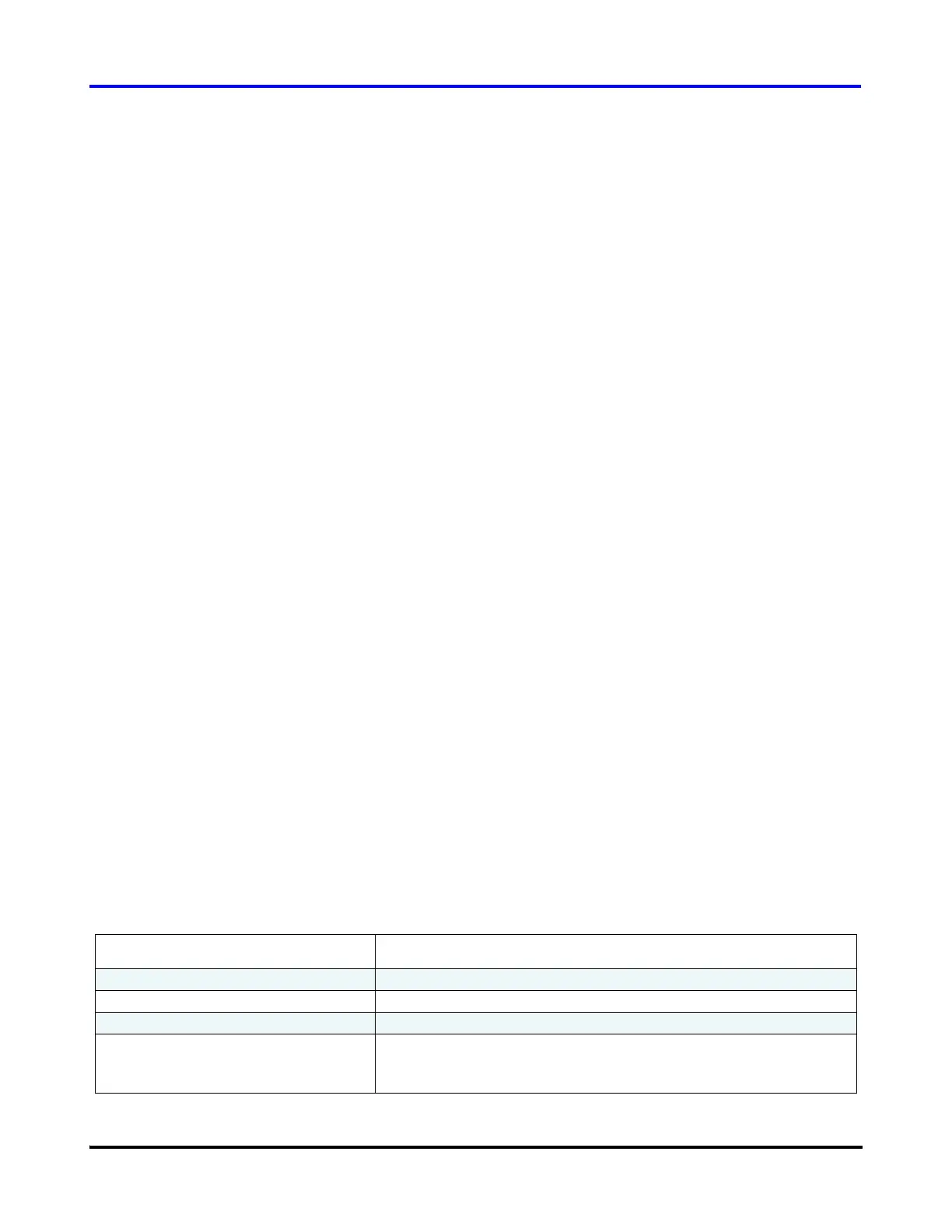
Table 7 Compressor Faults and Alarms
Fault / Alarm Possible Cause
Inverter Temperature Fault / Alarm Insufficient motor cooling
Discharge Temperature Fault / Alarm Insufficient charge (not enough gas)
Suction Pressure Fault / Alarm Insufficient charge or insufficient system load
Discharge Pressure Fault / Alarm Faulty condenser
Note: A “Discharge Pressure” fault will lock out the compressor.
The compressor will have to be powered down and restarted.

 Loading...


