Monitor Program Data and Controls
36 Danfoss Turbocor Compressors Inc.
ECD-00007M Rev. 1
6.7 Chiller Control
The “Chiller Control” window allows the user to control
one of the following:
• Leaving chiller water or air temperature
• Entering chiller water or air temperature
• Evaporating (saturated suction) temperature
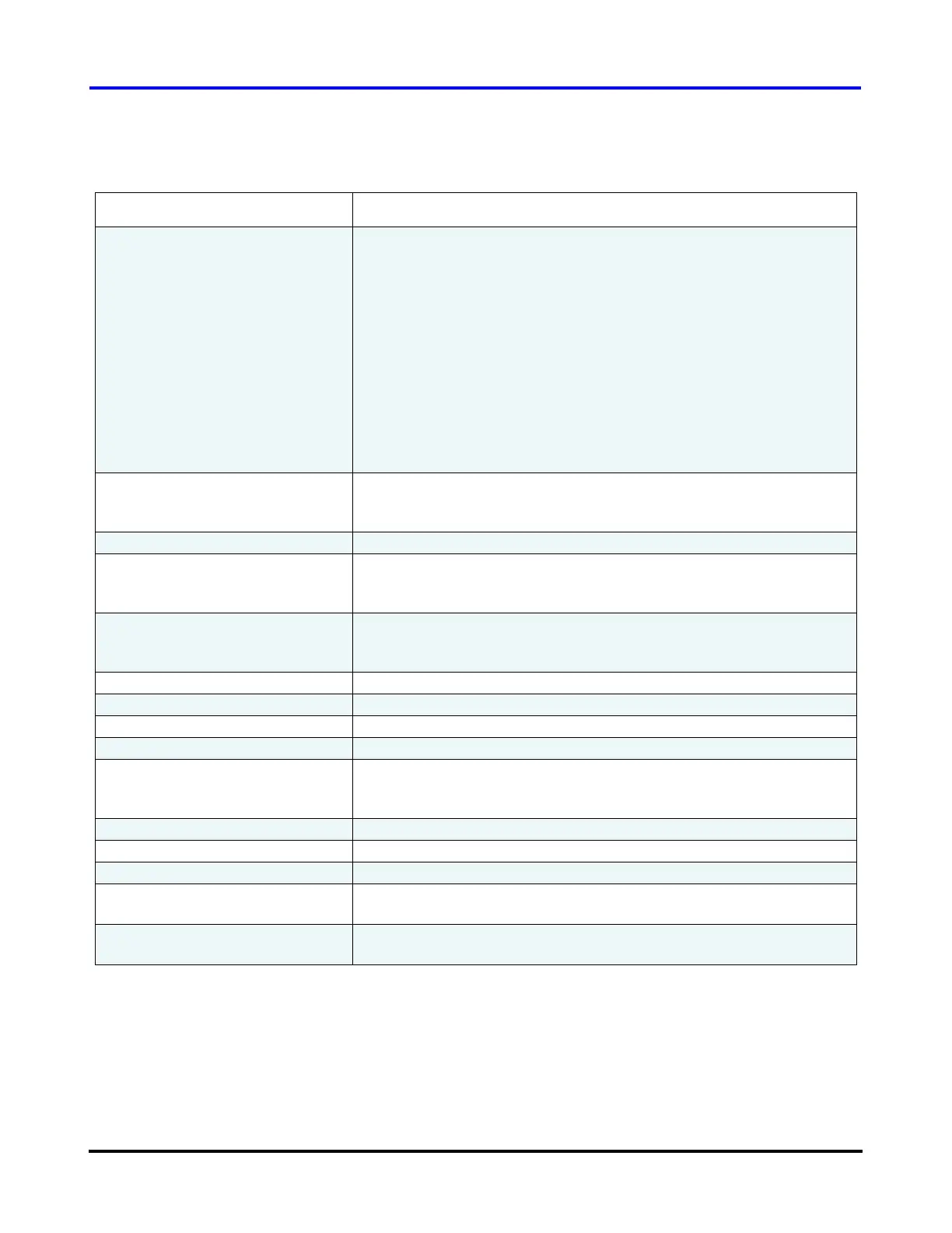
Table 13 Electronic Valve Data / Tuning Parameters (Analog Output)
Parameter Description
Control Mode Selects which control variable will be maintained by the 0 -10 VDC
output labeled “ANALOG” on the Chiller Interface module.
The options are:
• Load Balance Valve
• Discharge Pressure
• Inlet Guide Vane %
• Superheat – Flange TP
• Superheat – FlangeP, EWT
• Superheat – FlangeP, LIQT
• Suction Pressure
•Leaving Temp
• Entering Temp
•Liquid Temp
Auto/Manual Selects the compressor control mode. In automatic mode the
compressor has complete control over the stepper motor output. In
Manual mode the user is able to enter the valve position.
Analog Output % Actual percentage of the maximum voltage sent to the output.
Analog Output Starting % Percentage of maximum voltage sent to the terminals on start of the
compressor. The analog output will hold at this position until start delay
timer has expired.
Analog Output Start Delay Amount of time from compressor start to hold the voltage at the startup
percentage. Value is in seconds and starts to count down when the
drive enables.
Analog Setpoint Desired value of the controlled variable.
Analog Proportional Gain Controller Proportional Gain
Analog Integral Gain Controller Integral Gain
Analog Derivative Gain Controller Derivative Gain
Direct Acting/ Reverse Acting Control action.
Direct Acting: output increases as process variable increases.
Reverse Acting: output decreases as process variable increases.
Minimum Analog Output The minimum voltage output while the compressor is spinning.
Process Variable Value of the controlled variable.
Process Error Difference between the analog setpoint and the process variable.
Process Graph Plots the process variable (selected from the Control Mode) versus
time. Time is the PC system time, and is displayed in HH:MM format.
Output Graph Plots the percentage of the maximum output voltage versus time. Time
is the PC system time, and is displayed in HH:MM format.

 Loading...


