Service Monitor User Manual
Danfoss Turbocor Compressors Inc. 35
ECD-00007M Rev. 1
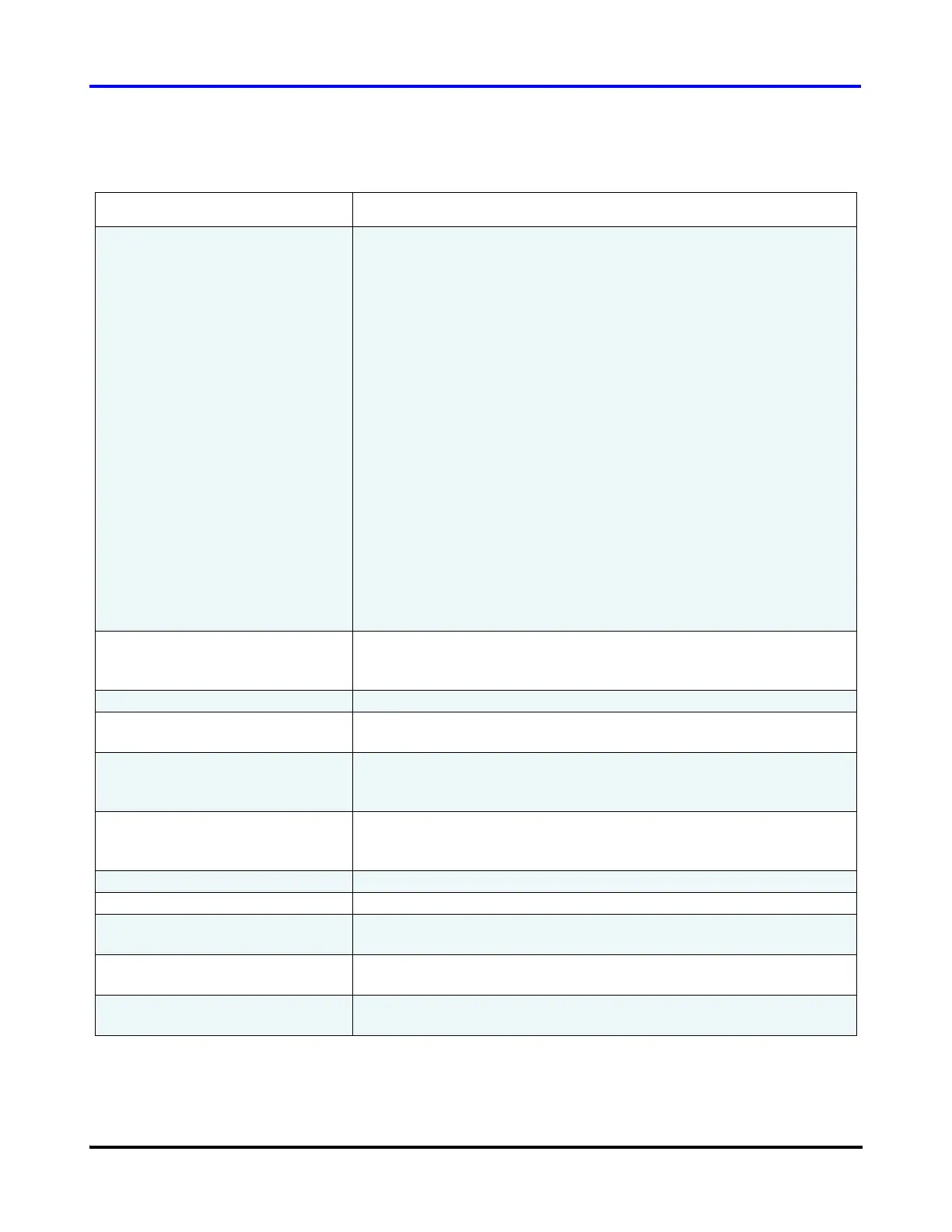
Table 12 Electronic Valve Data / Tuning Parameters (Stepper Motors)
Parameter Description
Control Mode Selects which control variable will be maintained by the stepper motor
output. The options are:
1. Superheat control using the compressor flange temperature and
pressure (this mode is not recommended as the temperature at the
compressor flange is influenced by external factors).
2. Superheat control using the compressor flange pressure and a
10K thermistor that is connected to the terminals labeled “ENTRY”
on the Chiller Interface module.
3. Superheat control using the compressor flange pressure and a
10K thermistor that is connected to the terminals labeled “LIQT” on
the Chiller Interface module.
4. Superheat control using an external temperature and pressure
sensor connected to the terminals labeled “SPARE T” & “SPARE
P” on the Chiller Interface module.
5. Liquid Level 1 control using a level sensor connected to the
terminals on the Chiller Interface module labeled “LIQ LEV1”.
6. Liquid Level 2 control using a level sensor connected to the
terminals on the Chiller Interface module labeled “LIQ LEV2”.
7. Load Balance control uses the compressor’s own internal control
algorithm to determine the best mix of speed control, inlet guide
vane opening and load balance valve opening.
Auto/Manual In automatic mode the compressor has complete control over the
stepper motor output. In Manual mode the user is able to enter the
valve position.
Process Value Value of the controlled variable selected from the Control Mode.
Valve % Open Ratio of the actual number of steps sent to the stepper motor over the
maximum number of steps the motor is allowed to drive.
Stepper Startup % Percentage of maximum steps sent to the motor on start of the
compressor. The stepper motor will hold at this position until the
stepper start delay timer has expired.
Stepper Start Position Delay Amount of time from compressor start to hold the number of steps sent
to the motor at the stepper startup %. Value is in seconds and starts to
count down when the drive enables.
Stepper Control Setpoint Desired value of the controlled variable.
Stepper Control Loop Speed Reaction time of the control loop to a process error.
Stepper Minimum Close % The minimum close position for the valve while the compressor is
spinning.
Maximum Step Count Number of steps from fully closed to fully open for the installed stepper
motor driven device.
Graph Displays the “Process Value” parameter with respect to time. The time
corresponds to the PC system time, and is displayed in HH:MM format.

 Loading...


