Analog output:
Number of programmable analog outputs 1
Terminal number 42
Current range at analog output 0/4 - 20 mA
Max. resistor load to common at analog output 500
Accuracy on analog output Max. error: 0.8 % of full scale
Resolution on analog output 8 bit
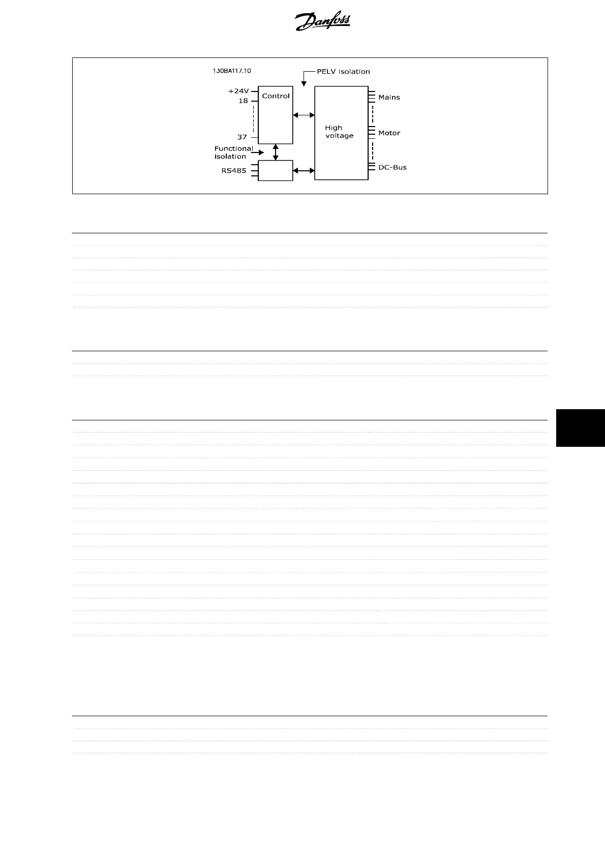
The analog output is galvanically isolated from the supply voltage (PELV) and other high-voltage terminals.
Control card, 24 V DC output:
Terminal number 12, 13
Max. load : 200 mA
The 24 V DC supply is galvanically isolated from the supply voltage (PELV), but has the same potential as the analog and digital inputs and outputs.
Relay outputs:
Programmable relay outputs 2
Relay 01 Terminal number 1-3 (break), 1-2 (make)
Max. terminal load (AC-1)
1)
on 1-3 (NC), 1-2 (NO) (Resistive load) 240 V AC, 2 A
Max. terminal load (AC-15)
1)
(Inductive load @ cos 0.4) 240 V AC, 0.2 A
Max. terminal load (DC-1)
1)
on 1-2 (NO), 1-3 (NC) (Resistive load) 60 V DC, 1A
Max. terminal load (DC-13)
1)
(Inductive load) 24 V DC, 0.1A
Relay 02 Terminal number 4-6 (break), 4-5 (make)
Max. terminal load (AC-1)
1)
on 4-5 (NO) (Resistive load)
2)3)
400 V AC, 2 A
Max. terminal load (AC-15)
1)
on 4-5 (NO) (Inductive load @ cos 0.4) 240 V AC, 0.2 A
Max. terminal load (DC-1)
1)
on 4-5 (NO) (Resistive load) 80 V DC, 2 A
Max. terminal load (DC-13)
1)
on 4-5 (NO) (Inductive load) 24 V DC, 0.1A
Max. terminal load (AC-1)
1)
on 4-6 (NC) (Resistive load) 240 V AC, 2 A
Max. terminal load (AC-15)
1)
on 4-6 (NC) (Inductive load @ cos 0.4) 240 V AC, 0.2A
Max. terminal load (DC-1)
1)
on 4-6 (NC) (Resistive load) 50 V DC, 2 A
Max. terminal load (DC-13)
1)
on 4-6 (NC) (Inductive load) 24 V DC, 0.1 A
Min. terminal load on 1-3 (NC), 1-2 (NO), 4-6 (NC), 4-5 (NO) 24 V DC 10 mA, 24 V AC 20 mA
Environment according to EN 60664-1 overvoltage category III/pollution degree 2
1) IEC 60947 part 4 and 5
The relay contacts are galvanically isolated from the rest of the circuit by reinforced isolation (PELV).
2) Overvoltage Category II
3) UL applications 300 V AC 2A
Control card, 10 V DC output:
Terminal number 50
Output voltage 10.5 V ±0.5 V
Max. load 25 mA
The 10 V DC supply is galvanically isolated from the supply voltage (PELV) and other high-voltage terminals.
VLT
®
AQUA Drive
Operating Instructions
10. Specifications
MG.20.M5.02 - VLT
®
is a registered Danfoss trademark
159
10

 Loading...


