5. Electrical installation
5.1. How to connect
5.1.1. Cables General
NB!
Always comply with national and local regulations on cable cross-sections.
Details of terminal tightening torques.
Power (kW) Torque (Nm)
Enclosure 200-240 V 380-480 V 525-600 V Line Motor
DC connec-
tion
Brake Earth Relay
A2 0.25 - 3.0 0.37 - 4.0 0.75 - 4.0 1.8 1.8 1.8 1.8 3 0.6
A3 3.7 5.5 - 7.5 5.5 - 7.5 1.8 1.8 1.8 1.8 3 0.6
A5 0.25 - 3.7 0.37 - 7.5 0.75 - 7.5 1.8 1.8 1.8 1.8 3 0.6
B1 5.5 - 11 11 - 18.5 - 1.8 1.8 1.5 1.5 3 0.6
B2
-
15
22
30
-
-
4.5
4.5
2)
4.5
4.5
2)
3.7
3.7
3.7
3.7
3
3
0.6
0.6
B3 5.5 - 11 11 - 18.5 11 - 18.5 1.8 1.8 1.8 1.8 3 0.6
B4 11 - 18.5 18.5 - 37 18.5 - 37 4.5 4.5 4.5 4.5 3 0.6
C1 18.5 - 30 37 - 55 - 10 10 10 10 3 0.6
C2
37
45
75
90
-
14
24
14
24
14
14
14
14
3
3
0.6
0.6
C3 18.5 - 30 37 - 55 37 - 55 10 10 10 10 3 0.6
C4 30 - 45 55 - 90 55 - 90
14/24
1
14/24
1
14 14 3 0.6
Table 5.1: Tightening of terminals
1. For different cable dimensions x/y where x≤95 mm
2
and y≥95 mm
2
.
2. Cable dimensions above 18.5 kW ≥ 35 mm
2
and below 22 kW ≤ 10 mm
2
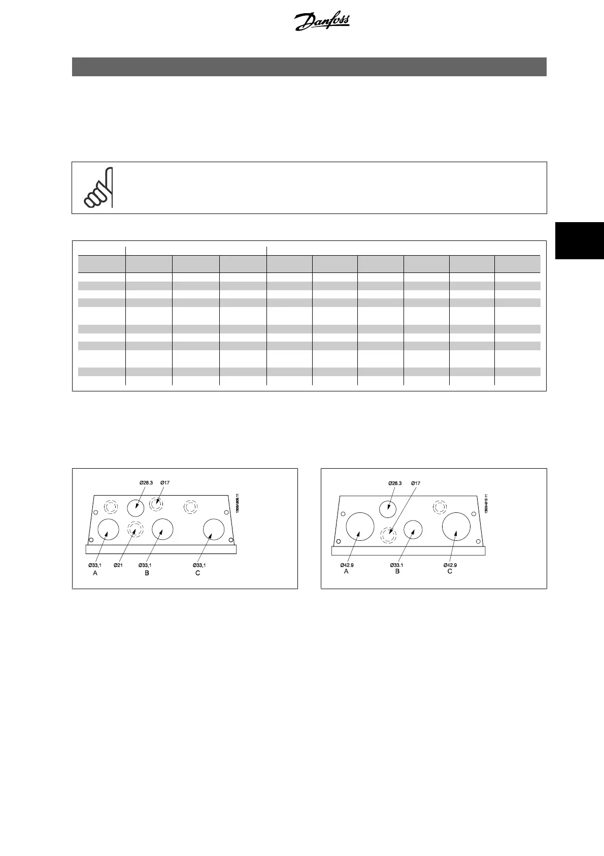
5.1.2. Enclosure Knock-outs
Illustration 5.1: Cable entry holes for enclosure B1. The suggested use
of the holes are purely recommendations and other solutions are pos-
sible.
Illustration 5.2: Cable entry holes for enclosure B2. The suggested use
of the holes are purely recommendations and other solutions are pos-
sible.
VLT
®
AQUA Drive
Operating Instructions
5. Electrical installation
MG.20.M5.02 - VLT
®
is a registered Danfoss trademark
19
5

 Loading...


