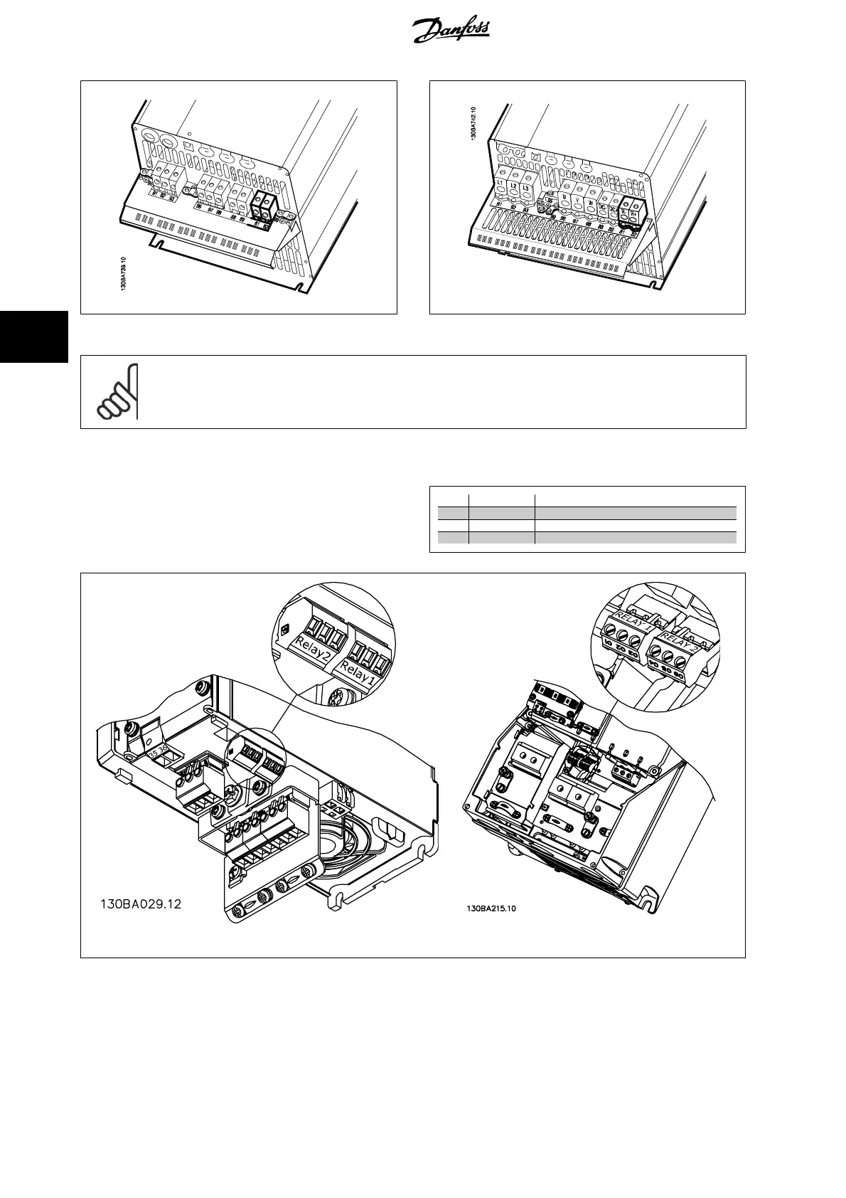
Illustration 5.35: Brake connection terminal for C3. Illustration 5.36: Brake connection terminal for C4.
NB!
If a short circuit in the brake IGBT occurs, prevent power dissipation in the brake resistor by using a mains switch or contactor to
disconnect the mains for the frequency converter. Only the frequency converter shall control the contactor.
5.1.21. Relay Connection
To set relay output, see par. group 5-4* Relays.
No.
01 - 02 make (normally open)
01 - 03 break (normally closed)
04 - 05 make (normally open)
04 - 06 break (normally closed)
Terminals for relay connection
(A2 and A3 enclosures).
Terminals for relay connection
(A5, B1 and B2 enclosures).
5. Electrical installation
VLT
®
AQUA Drive
Operating Instructions
36
MG.20.M5.02 - VLT
®
is a registered Danfoss trademark
5

 Loading...


