22-76 Interval Between Starts
Range: Function:
0 s
*
[0 - 3600 s] Sets the time desired as minimum time between two starts. Any
normal start command (Start/Jog/Freeze) will be disregarded
until the timer has expired.
22-77 Minimum Run Time
Range: Function:
0 s
*
[0 - par. 22-76] Sets the time desired as minimum run time after a normal start
command (Start/Jog/Freeze). Any normal stop command will be
disregarded until the set time has expired. The timer will start
counting following a normal start command (Start/Jog/Freeze).
The timer will be overridden by a Coast (Inverse) or an External
Interlock command.
NB!
Does not work in cascade mode.
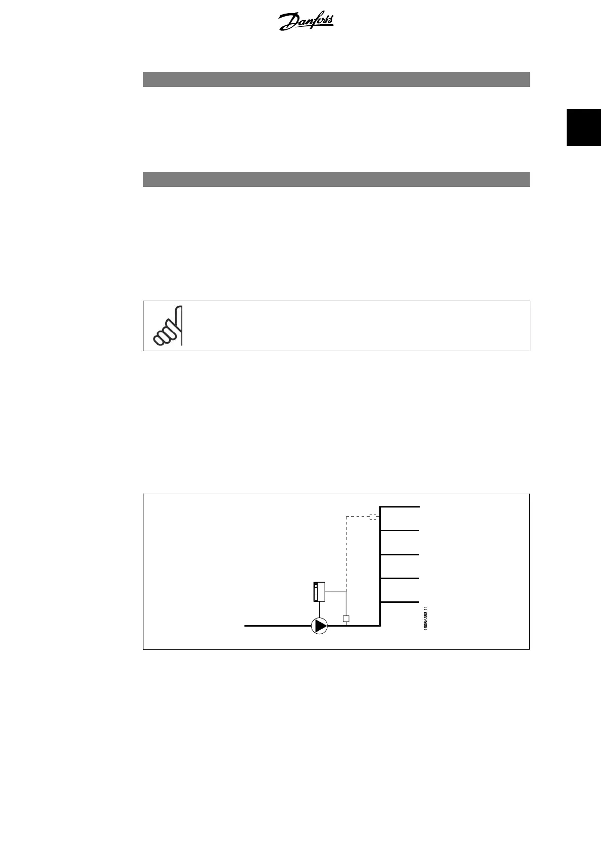
2.19.7. Flow Compensation, 22-8*
It is sometimes the case that is not possible for a pressure transducer to be placed at a remote
point in the system and it can only be located close to the fan/pump outlet. Flow compensation
operates by adjusting the set-point according to the output frequency, which is almost proportional
to flow, thus compensating for higher losses at higher flow rates.
H
DESIGN
(Required pressure) is the setpoint for closed loop (PI) operation of the frequency con-
verter and is set as for closed loop operation without flow compensation.
There are two methods which can be employed, depending upon whether or not the Speed at
System design Working Point is known.
VLT
®
AQUA Drive Programming Guide 2. Parameter Description
MG.20.O2.02 - VLT
®
is a registered Danfoss trademark
207
2
 Loading...


