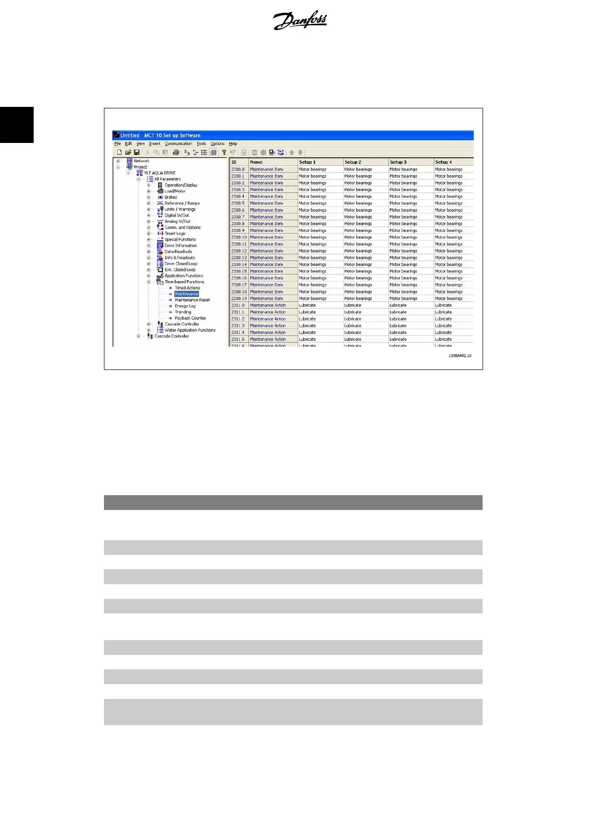
Preventive Maintenance can be programmed from the LCP, but use of the PC-based VLT Motion
Control Tool MCT10 is recommended.
The LCP indicates (with a wrench-icon and an “M”) when it is time for a Preventive Maintenance
Action, and can be programmed to be indicated on a digital output in parameter group 5-3*. The
Preventive Maintenance Status may be read in par. 16-96
Prev. Maintenance Word
. A Preventive
Maintenance indication can be reset from a digital input, the FC bus or manually from the Local
Control Panel through par. 23-15
Reset Maintenance Word
.
A Maintenance Log with the latest 10 loggings can be read from parameter group 18-0* and via
the Alarm log button on the LCP after selecting Maintenance Log.
23-10 Maintenance Item
Option: Function:
[1]
*
Motor bearings
[2] Fan bearings
[3] Pump bearings
[4] Valve
[5] Pressure transmitter
[6] Flow transmitter
[7] Temperature trans-
mitter
[8] Pump seals
[9] Fan belt
[10] Filter
[11] Drive cooling fan
[12] Drive system health
check
2. Parameter Description VLT
®
AQUA Drive Programming Guide
216
MG.20.O2.02 - VLT
®
is a registered Danfoss trademark
2
 Loading...


