Status display I
This read-out state is standard after start-up
or initialization.
Use [INFO] to obtain information about the
value/measurement linked to the displayed
operating variables (1.1, 1.2, 1.3, 2, and 3).
See the operating variables shown in the dis-
play in this illustration. 1.1, 1.2 and 1.3 are
shown in small size. 2 and 3 are shown in me-
dium size.
130BP041.10
1.1
1.3
2
1.2
3
Status display II
See the operating variables (1.1, 1.2, 1.3, and
2) shown in the display in this illustration.
In the example, Speed, Motor current, Motor
power and Frequency are selected as varia-
bles in the first and second lines.
1.1, 1.2 and 1.3 are shown in small size. 2 is
shown in large size.
130BP062.10
2
1.2
1.3
1.1
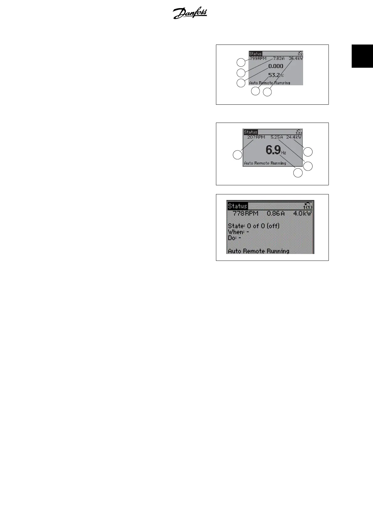
Status display III:
This state displays the event and action of the
Smart Logic Control. For further information,
see section
Smart Logic Control
.
130BP063.10
VLT
®
AQUA Drive Programming Guide 1. How to Programme
MG.20.O2.02 - VLT
®
is a registered Danfoss trademark
5
1

 Loading...


