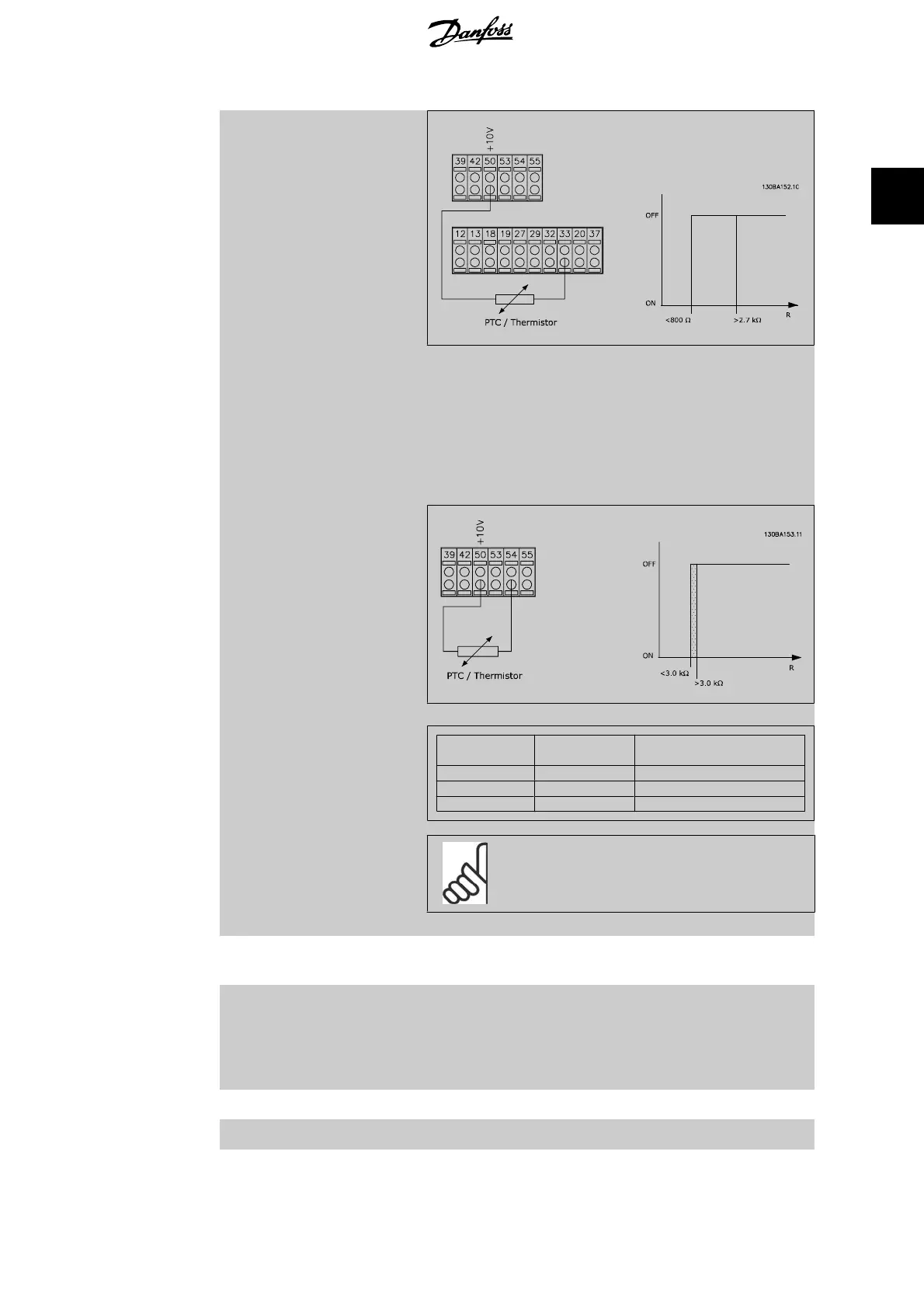
Using an analog input and 10 V as power supply:
Example: The frequency converter trips when the motor tem-
perature is too high.
Parameter set-up:
Set Par. 1-90
Motor Thermal Protection
to
Thermistor Trip
[2]
Set Par. 1-93
Thermistor Source
to
Analog Input 54
[2]
Do not select a reference source.
Input
Digital/analog
Supply Voltage
Volt
Threshold
Cut-out Values
Digital 24 V < 6.6 kΩ - > 10.8 kΩ
Digital 10 V < 800Ω - > 2.7 kΩ
Analog 10 V < 3.0 kΩ - > 3.0 kΩ
NB!
Check that the chosen supply voltage follows the
specification of the used thermistor element.
[3] ETR warning 1
ETR Warning 1-4
, activate a warning on the display when the
motor is overloaded.
[4]
*
ETR trip 1
ETR Trip 1-4
trip the frequency converter when the motor is
overloaded.
Programme a warning signal via one of the digital outputs. The
signal appears in the event of a warning and if the frequency
converter trips (thermal warning).
[5] ETR warning 2 See [3]
[6] ETR trip 2 See [4]
VLT
®
AQUA Drive Programming Guide 2. Parameter Description
MG.20.O2.02 - VLT
®
is a registered Danfoss trademark
55
2
 Loading...


