2.8.4. 6-1* Analog Input 1
Parameters for configuring the scaling and limits for analog input 1 (terminal 53).
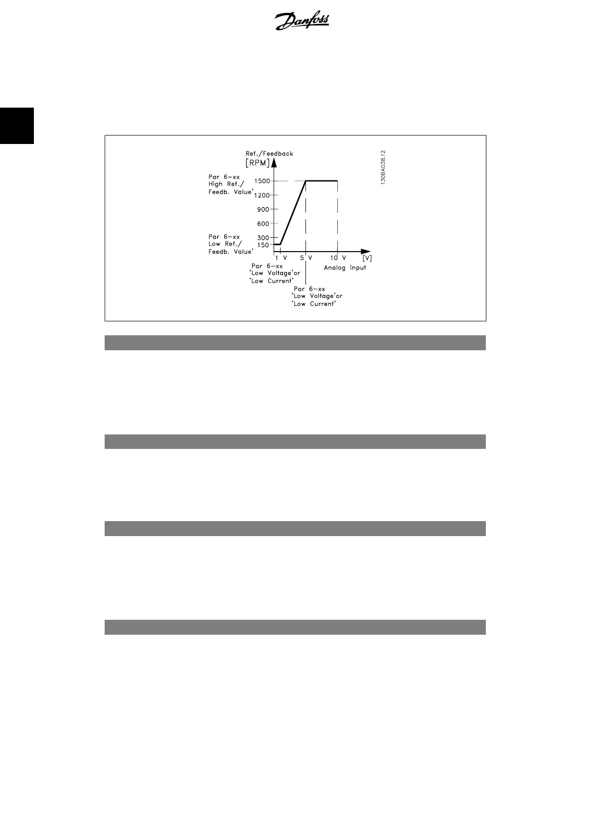
6-10 Terminal 53 Low Voltage
Range: Function:
0.07V
*
[0.00 - par. 6-11] Enter the low voltage value. This analog input scaling value
should correspond to the low reference/feedback value set in
par. 6-14.
6-11 Terminal 53 High Voltage
Range: Function:
10.0V
*
[Par. 6-10 to 10.0 V] Enter the high voltage value. This analog input scaling value
should correspond to the high reference/feedback value set in
par. 6-15.
6-12 Terminal 53 Low Current
Range: Function:
4 mA
*
[0.0 to par. 6-13 mA] Enter the low current value. This reference signal should corre-
spond to the low reference/feedback value, set in par. 6-14. The
value must be set at >2 mA in order to activate the Live Zero
Time-out Function in par. 6-01.
6-13 Terminal 53 High Current
Range: Function:
20.0
mA
*
[ Par. 6-12 to - 20.0
mA]
Enter the high current value corresponding to the high refer-
ence/feedback set in par. 6-15.
2. Parameter Description VLT
®
AQUA Drive Programming Guide
98
MG.20.O2.02 - VLT
®
is a registered Danfoss trademark
2
 Loading...


