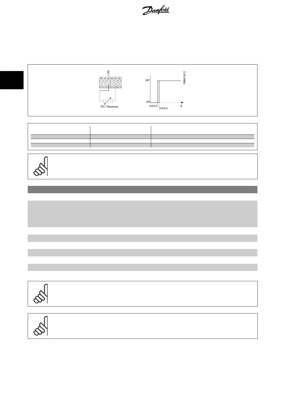
Using an analog input and 10 V as power supply:
Example: The frequency converter trips when the motor temperature is too high.
Parameter set-up:
Set par. 1-90
Motor Thermal Protection
to
Thermistor Trip
[2]
Set par. 1-93
Thermistor Source
to
Analog Input 54
[2]
Input
Digital/analog
Supply Voltage
Volt
Threshold
Cut-out Values
Digital 24 V < 6.6 kΩ - > 10.8 kΩ
Digital 10 V < 800Ω - > 2.7 kΩ
Analog 10 V
< 3.0 kΩ - > 3.0 kΩ
NB!
Check that the chosen supply voltage follows the specification of the used thermistor element.
1-93 Thermistor Source
Option: Function:
Select the input to which the thermistor (PTC sensor) should be connected. An analog input option
[1] or [2] cannot be selected if the analog input is already in use as a reference source (selected in
par. 3-15
Reference 1 Source
, par. 3-16
Reference 2 Source
or par. 3-17
Reference 3 Source
).
When using MCB 112, choice [0]
None
must always be selected.
[0] * None
[1] Analog input 53
[2] Analog input 54
[3] Digital input 18
[4] Digital input 19
[5] Digital input 32
[6] Digital input 33
NB!
This parameter cannot be adjusted while the motor is running.
NB!
Digital input should be set to [0]
PNP - Active at 24V
in par. 5-00.
3 Parameter descriptions FC 300 Programming Guide
62
MG.33.M8.02 - VLT
®
is a registered Danfoss trademark
3

 Loading...


