1.6.1 Block Diagram of the Frequency
Converter
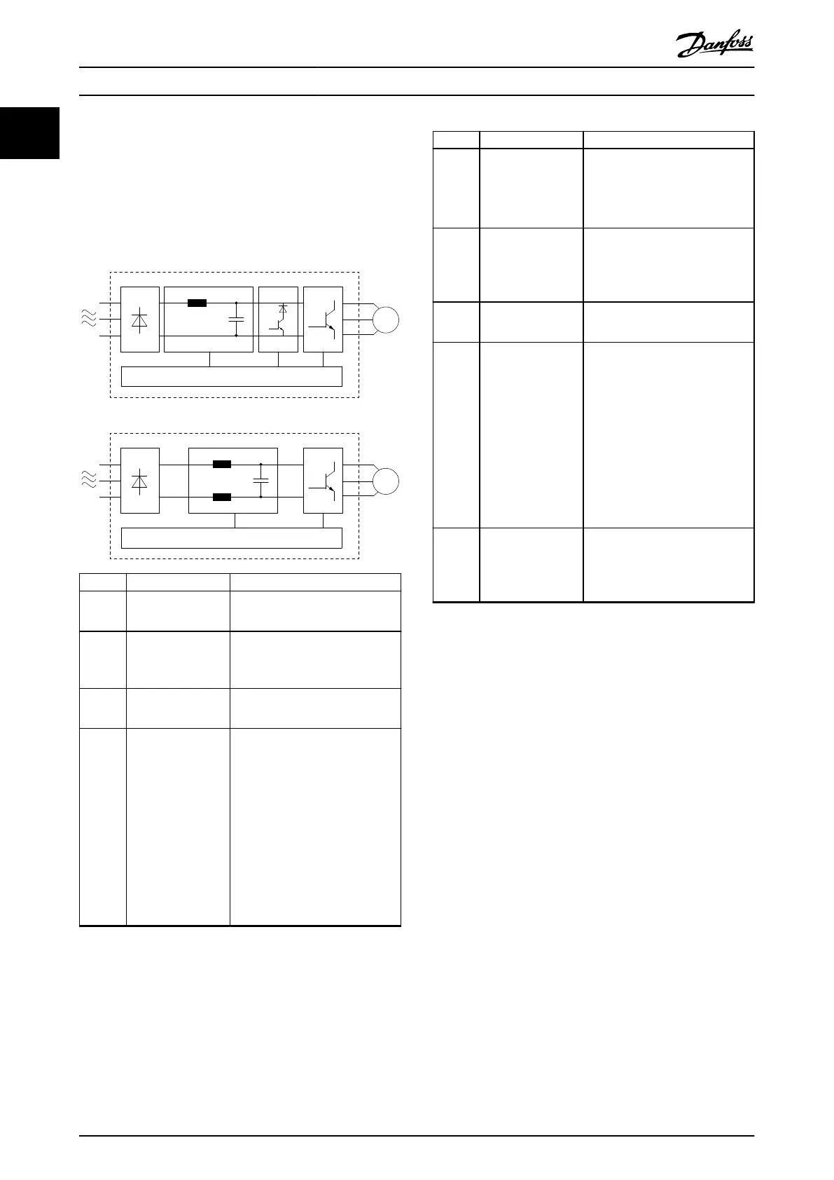
Illustration 1.1 is a block diagram of the internal
components of the frequency converter.
M
7
63
4
5
21
8
130BF760.10
4
M
7
63
4
5
21
8
9
J1–J5
J6–J7
Area Component Functions
1 Mains input
•
AC mains supply to the
frequency converter.
2 Rectier
•
The rectier bridge converts
the AC input to DC current to
supply inverter power.
3 DC bus
•
Intermediate DC-bus circuit
handles the DC current.
4 DC reactor
•
Filters the intermediate DC
circuit current.
•
Provides mains transient
protection.
•
Reduces the root mean square
(RMS) current.
•
Raises the power factor
reected back to the line.
•
Reduces harmonics on the AC
input.
Area Component Functions
5 Capacitor bank
•
Stores the DC power.
•
Provides ride-through
protection for short power
losses.
6 Inverter
•
Converts the DC into a
controlled PWM AC waveform
for a controlled variable
output to the motor.
7 Output to motor
•
Regulated 3-phase output
power to the motor.
8 Control circuitry
•
Input power, internal
processing, output, and motor
current are monitored to
provide ecient operation
and control.
•
User interface and external
commands are monitored and
performed.
•
Status output and control can
be provided.
9 Brake chopper
•
Brake chopper is used in the
DC intermediate circuit to
control DC voltage when the
load feeds energy back.
Illustration 1.1 Example of Block Diagram for a Frequency
Converter
Introduction
VLT
®
AutomationDrive FC 360
4 Danfoss A/S © 03/2017 All rights reserved. MG06A702
11

 Loading...


