2.7.3 EMC Test Results
The following test results have been obtained using a system with a frequency converter, a screened control cable, a control
box with potentiometer, and a motor screened cable.
RFI
lter
type
Conduct emission. Maximum screened cable length [m] Radiated emission
Industrial environment
Housing, trades, and
light industries
Industrial
environment
Housing, trades, and
light industries
EN 55011 Class A2 EN 55011 Class A1 EN 55011 Class B EN 55011 Class A1 EN 55011 Class B
Without
external
lter
With
external
lter
Without
external
lter
With
external
lter
Without
external
lter
With
external
lter
Without
external
lter
With
external
lter
Without
external
lter
With
external
lter
H4 RFI lter (Class A1)
CDS
803
IP20
– – 25 50 – 20 Yes Yes – No
Table 2.6 Test Results
2.8 Harmonics
2.8.1 Overview of Harmonics Emission
A frequency converter takes up a non-sinusoidal current
from mains, which increases the input current I
RMS
. A non-
sinusoidal current is transformed with a Fourier analysis
and split into sine-wave currents with dierent frequencies,
that is, dierent harmonic currents I
n
with 50 Hz basic
frequency:
I
1
I
5
I
7
Hz 50 250 350
Table 2.7 Harmonic Currents
The harmonics do not aect the power consumption
directly, but increase the heat losses in the installation
(transformer, cables). So, in plants with a high percentage
of rectier load, maintain harmonic currents at a low level
to avoid overload of the transformer and high temperature
in the cables.
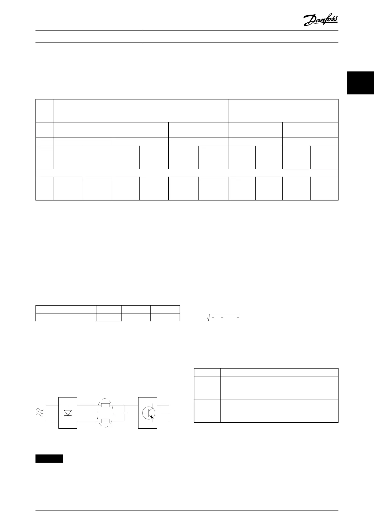
Illustration 2.8 Intermediate Circuit Coils
NOTICE
Some of the harmonic currents might disturb communi-
cation equipment connected to the same transformer or
cause resonance with power factor correction batteries.
To ensure low harmonic currents, the frequency converter
is equipped with intermediate circuit coils as standard. This
normally reduces the input current I
RMS
by 40%.
The voltage distortion on the mains supply voltage
depends on the size of the harmonic currents multiplied
by the mains impedance for the frequency in question. The
total voltage distortion THD is calculated based on the
individual voltage harmonics using this formula:
THD % = U
2
5
+ U
2
7
+ ... + U
2
N
(U
N
% of U)
2.8.2 Harmonics Emission Requirements
Equipment connected to the public supply network
Options Denition
1 IEC/EN 61000-3-2 Class A for 3-phase balanced
equipment (for professional equipment only up to 1
kW total power).
2 IEC/EN 61000-3-12 Equipment 16–75 A and profes-
sional equipment as from 1 kW up to 16 A phase
current.
Table 2.8 Connected Equipment
Product Overview Design Guide
MG18N202 Danfoss A/S © 12/2015 All rights reserved. 21
2 2