7 RS485 Installation and Set-up
7.1 RS485
7.1.1 Overview
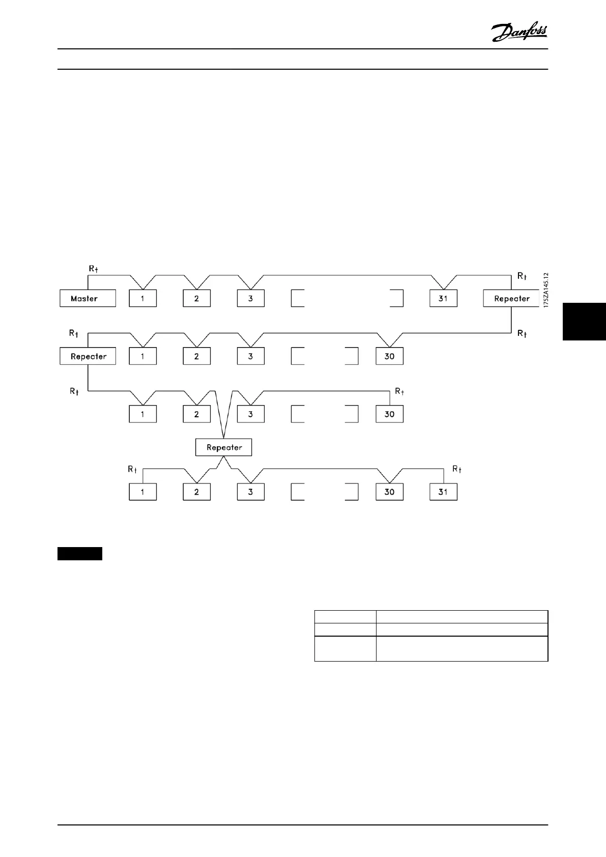
RS485 is a 2-wire bus interface compatible with multi-drop network topology, that is, nodes can be connected as a bus, or
via drop cables from a common trunk line. A total of 32 nodes can be connected to 1 network segment.
Repeaters divide network segments, see Illustration 7.1.
Illustration 7.1 RS485 Bus Interface
NOTICE
Each repeater functions as a node within the segment in
which it is installed. Each node connected within a given
network must have a unique node address across all
segments.
Terminate each segment at both ends, using either the
termination switch (S801) of the frequency converters or a
biased termination resistor network. Always use screened
twisted pair (STP) cable for bus cabling, and follow good
common installation practice.
Low-impedance ground connection of the screen at every
node is important, including at high frequencies. Thus,
connect a large surface of the screen to ground, for
example with a cable clamp or a conductive cable gland. It
may be necessary to apply potential-equalising cables to
maintain the same earth potential throughout the network
- particularly in installations with long cables.
To prevent impedance mismatch, always use the same
type of cable throughout the entire network. When
connecting a motor to the frequency converter, always use
screened motor cable.
Cable Screened twisted pair (STP)
Impedance [Ω]
120
Cable length
[m]
Maximum 1200 (including drop lines)
Maximum 500 station-to-station
Table 7.1 Cable Specications
RS485 Installation and Set-... Design Guide
MG18N202 Danfoss A/S © 12/2015 All rights reserved. 49
7 7