-DC+DC
BR- BR+ U V W
99
M A I N S
95
RELAY 1 RELAY 2
- LC +
130BA261.10
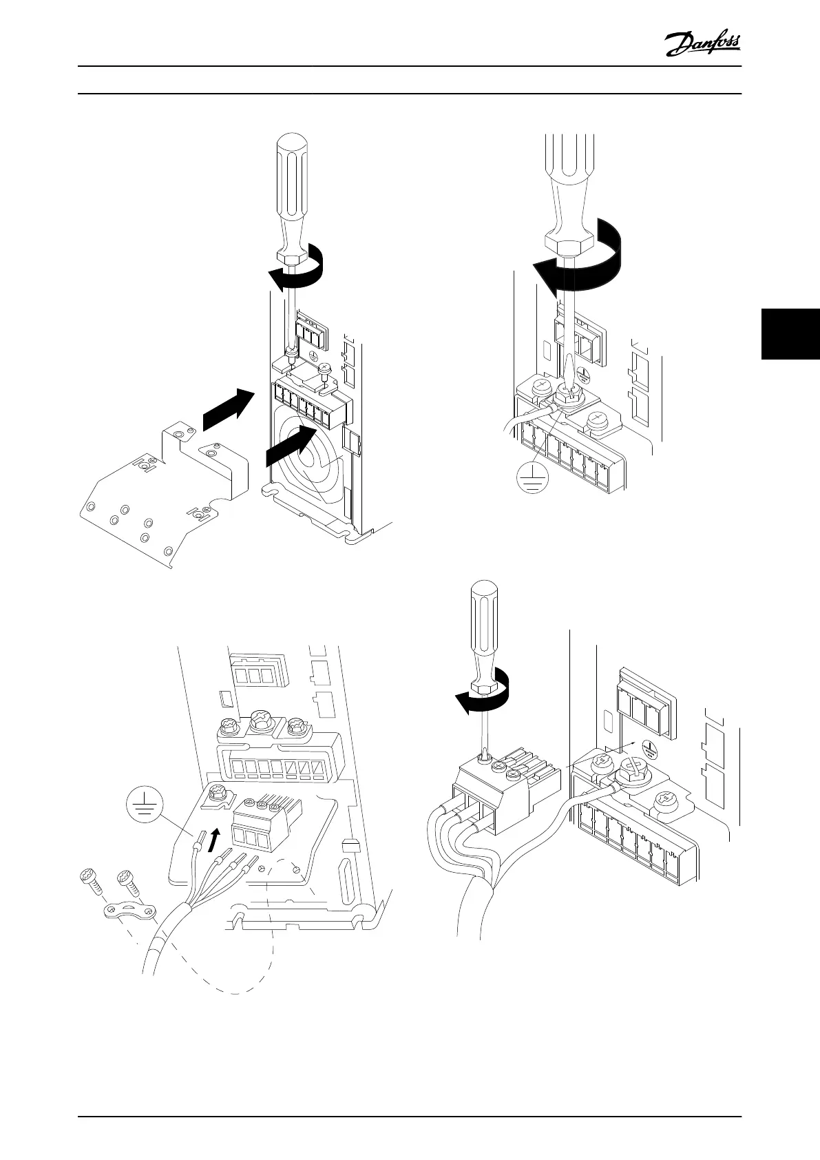
Illustration 5.3 Mount the 2 screws in the mounting plate,
slide it into place and tighten fully.
MOTOR
MOTOR
U V W
99
130BT302.12
Illustration 5.4 H3–H5 Enclosure
130BA262.10
M
I N S
+DC
BR-
BR+
U
V
W
RELAY 1 RELAY 2
95
Illustration 5.5 When mounting cables, rst mount and tighten
the ground cable.
130BA263.10
95
M
A
INS
+DC
BR-
BR+
U
V
W
91
92
93
L1
L2
L3
RELAY 1 RELAY 2
Illustration 5.6 Mount mains plug and tighten wires.
How to Install Design Guide
MG18N202 Danfoss A/S © 12/2015 All rights reserved. 33
5 5