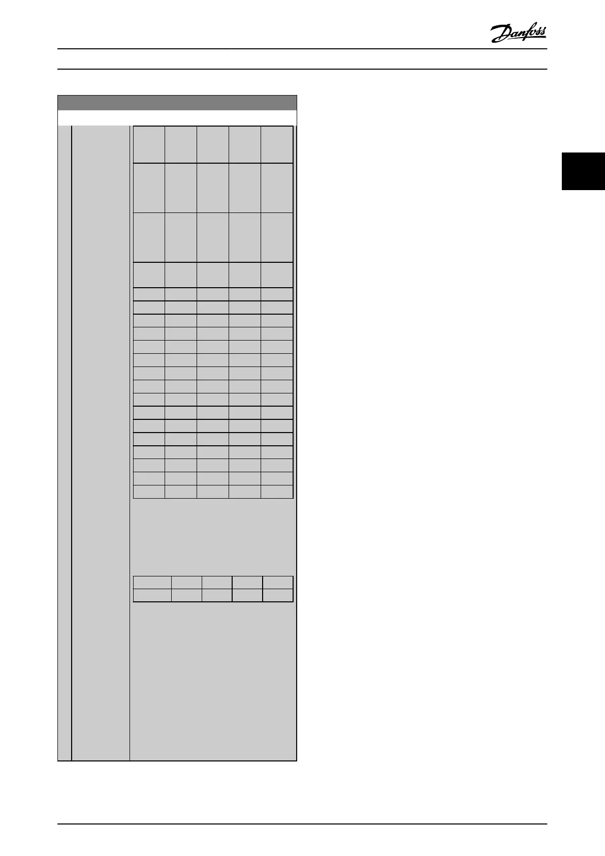
16-96 Maintenance Word
Range: Function:
Positio
n
4⇒
Valve Fan
bea-
rings
Pump
bea-
rings
Motor
bea-
rings
Positio
n
3 ⇒
Pump
seals
Tempe-
rature
transmi
tter
Flow
trans-
mitter
Pressur
e
transmi
tter
Positio
n
2 ⇒
Drive
system
health
check
Drive
cooling
fan
Filter Fan
belt
Positio
n
1⇒
Warrant
y
0
hex
- - - -
1
hex
- - - +
2
hex
- - + -
3
hex
- - + +
4
hex
- + - -
5
hex
- + - +
6
hex
- + + -
7
hex
- + + +
8
hex
+ - - -
9
hex
+ - - +
A
hex
+ - + -
B
hex
+ - + +
C
hex
+ + - -
D
hex
+ + - +
E
hex
+ + + -
F
hex
+ + + +
Table 3.23
Example:
The
Preventive Maintenance Word shows
040Ahex.
Position 1 2 3 4
hex-value 0 4 0 A
Table 3.24
The
first digit 0 indicates that no items from
the fourth row requires maintenance
The second digit 4 refers to the third row
indicating that the Drive Cooling Fan requires
maintenance
The third digit 0 indicates that no items from
the second row requires maintenance
The fourth digit A refers to the top row
indicating that the Valve and the Pump
Bearings require maintenance
Parameter Description
VLT
®
Refrigeration Drive Programming Guide
MG16H102 - VLT
®
is a registered Danfoss trademark
109
3 3
 Loading...


