5.1.5 Fault Messages
WARNING 1, 10 Volts low
The
10 V voltage from terminal 50 on the control card is
below 10 V.
Remove some of the load from terminal 50, as the 10 V
supply is overloaded. Max. 15 mA or minimum 590 Ω.
WARNING/ALARM 2, Live zero error
The signal on terminal 53 or 54 is less than 50% of the
value set in 6-10 Terminal 53 Low Voltage, 6-12 Terminal 53
Low Current, 6-20 Terminal 54 Low Voltage or 6-22 Terminal
54 Low Current respectively.
WARNING/ALARM 3, No motor
No motor has been connected to the output of the
frequency converter.
WARNING/ALARM 4, Mains phase loss
A phase is missing on the supply side, or the mains
voltage imbalance is too high.
This message also appears in case of a fault in the input
rectifier on the frequency converter.
Check the supply voltage and supply currents to the
frequency converter.
WARNING 5, DC link voltage high
The intermediate circuit voltage (DC) is higher than the
overvoltage limit of the control system. The frequency
converter is still active.
WARNING 6, DC link voltage low
The intermediate circuit voltage (DC) is below the
undervoltage limit of the control system. The frequency
converter is still active.
WARNING/ALARM 7, DC over voltage
If the intermediate circuit voltage exceeds the limit, the
frequency converter trips after a time.
Possible corrections:
Select
Over Voltage Control function in 2-17
Over-
voltage Control
Connect a brake resistor
Extend the ramp time
Activate functions in 2-10 Brake Function
Increase 14-26 Trip Delay at Inverter Fault
Selecting OVC function will extend the ramp times.
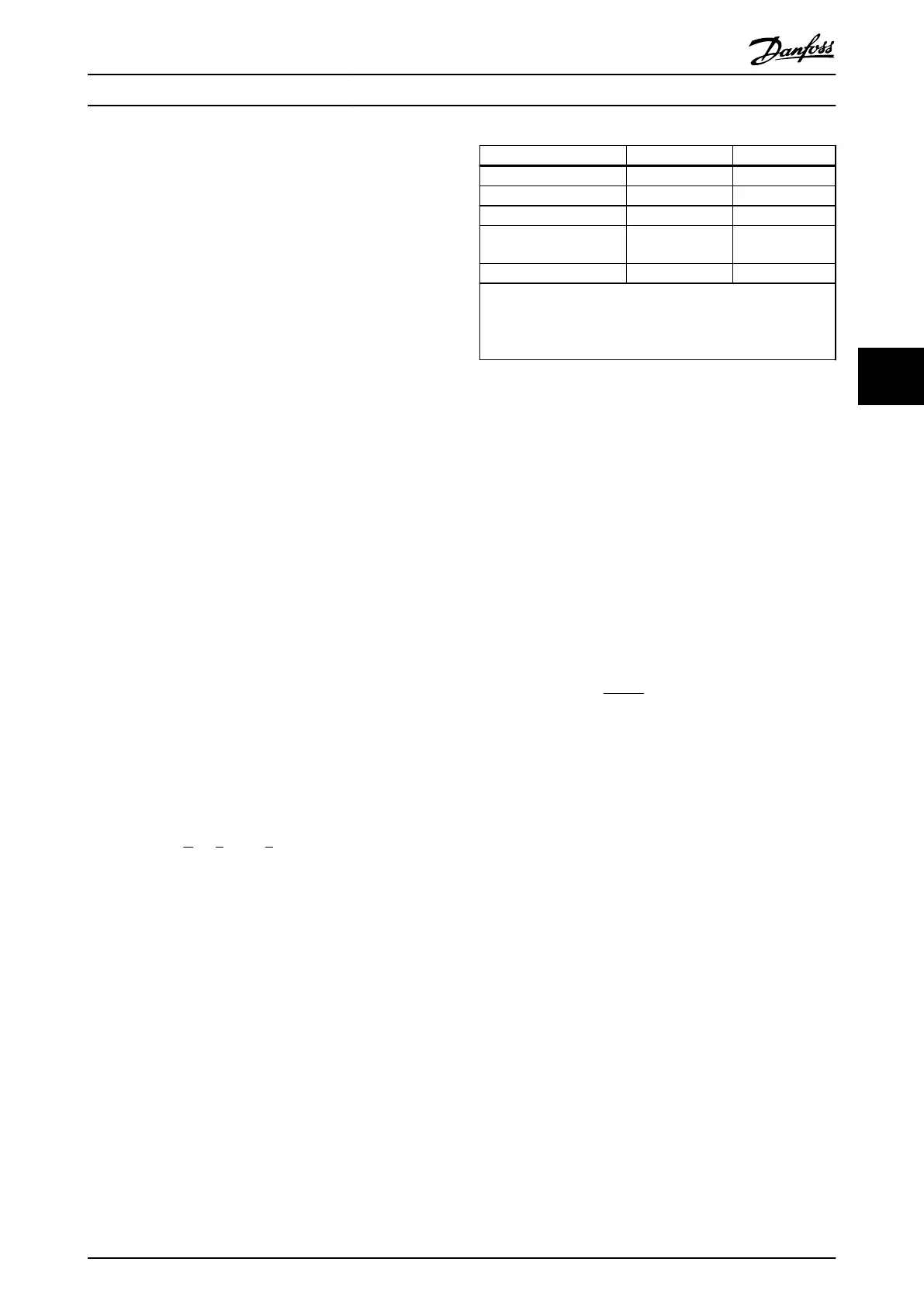
FC 103 3 x 200-240 V AC 3 x 380-500 V AC
[V DC] [V DC]
Undervoltage 185 373
Voltage warning low 205 410
Voltage warning high
(w/o
brake - w/brake)
390/405 810/840
Overvoltage 410 855
The voltages stated are the intermediate circuit voltage of the
frequency
converter with a tolerance of ±5 %. The
corresponding mains voltage is the intermediate circuit voltage
(DC-link) divided by 1.35
Table 5.11 Alarm/Warning Limits
WARNING/ALARM
8, DC under voltage
If the intermediate circuit voltage (DC) drops below the
“voltage warning low” limit (see Table 5.11), the frequency
converter checks if 24 V backup supply is connected.
If no 24 V backup supply is connected, the frequency
converter trips after a given time depending on the unit.
To check whether the supply voltage matches the
frequency converter, see General Specifications in the VLT
Refrigeration Drive FC 103 Design Guide.
WARNING/ALARM 9, Inverter overloaded
The frequency converter is about to cut out because of an
overload (too high current for too long). The counter for
electronic, thermal inverter protection gives a warning at
98% and trips at 100%, while giving an alarm. The
frequency converter
cannot be reset until the counter is
below
90%.
The fault is that the frequency converter is overloaded by
more than nominal current for too long.
WARNING/ALARM 10, Motor ETR over temperature
According to the electronic thermal protection (ETR), the
motor is too hot. You can choose if you want the
frequency converter to give a warning or an alarm when
the counter reaches 100% in 1-90 Motor Thermal Protection.
The fault is that the motor is overloaded by more than
nominal current for too long. Check that 1-24 Motor
Current is set correctly.
WARNING/ALARM 11, Motor thermistor over temp
The thermistor or the thermistor connection is discon-
nected. You can choose if you want the frequency
converter to give a warning or an alarm in 1-90 Motor
Thermal Protection. Check that the thermistor is connected
correctly between terminal 53 or 54 (analog voltage input)
and terminal 50 (+ 10 V supply), or between terminal 18 or
19 (digital input PNP only) and terminal 50. If a KTY sensor
is used, check for correct connection between terminal 54
and 55.
WARNING/ALARM 12, Torque limit
The torque is higher than the value in 4-16 Torque Limit
Motor Mode (in motor operation) or the torque is higher
than the value in 4-17 Torque Limit Generator Mode (in
regenerative operation).
Troubleshooting
VLT
®
Refrigeration Drive Programming Guide
MG16H102 - VLT
®
is a registered Danfoss trademark
195
5 5
 Loading...


